
RESEARCH ARTICLE
Comparative and Microscopic Analysis of Vehicle Startup Behavior in Red Countdown Traffic Lights with Various Display Forms
Motohiro Fujita1, *
Article Information

Identifiers and Pagination:
Year: 2024Volume: 18
E-location ID: e26671212279478
Publisher ID: e26671212279478
DOI: 10.2174/0126671212279478240105114915
Article History:
Received Date: 04/09/2023Revision Received Date: 21/11/2023
Acceptance Date: 11/12/2023
Electronic publication date: 22/01/2024
Collection year: 2024

open-access license: This is an open access article distributed under the terms of the Creative Commons Attribution 4.0 International Public License (CC-BY 4.0), a copy of which is available at: https://creativecommons.org/licenses/by/4.0/legalcode. This license permits unrestricted use, distribution, and reproduction in any medium, provided the original author and source are credited.
Abstract
Background
Countdown-type traffic lights provide drivers with the time remaining before the signal turns green or red. Most countdown devices inform the drivers of the exact signal switching time numerically on a display form. This study focuses on two vehicle startup behaviors when a red signal phase countdown (RC) is displayed: a premature start (PS) and an early reaction (ER). The PS is a vehicle crossing the stop line before the green phase, and the ER is a vehicle starting to move before the green phase. While there are many studies on PS rates under RC, there are only a few studies on ER rates. There are also few studies that have analyzed the relationship between the PS and ER rates and the display forms of RC have also been analyzed in terms of micro-behavior.
Objective
This study microscopically analyzes the ER and PS by including data within 1 second at signal switching while comparing 10 types of display forms in RC in order to obtain the ideas of safer and more efficient display forms in signal countdown.
Methods
We conducted the experiments with RC traffic lights of different display forms, and the surveys of no countdown (NC).
Results
From the very limited conditions of the experiment, we found that there is a threshold at which the ER rates in RC and NC differ significantly.
Conclusion
We were also able to analyze the basic characteristics related to the display forms of RC, which is a quick start and which reduces PS and ER.
1. INTRODUCTION
Currently, countdown-type traffic lights provide drivers with the time remaining for the traffic lights to switch to green or red. Most commonly, countdown devices inform drivers of the exact signal switching time, such as 1-s decrements, on a display installed next to or above the signal lamp. Although a driver changes vehicle behavior based on the countdown, the driver can change his/her startup behavior to a safer and more efficient one by devising the methods and forms displayed by the countdown. Countdown information from traffic lights has good effects in controlling traffic, especially on startup behavior. When countdown information is presented during the red-signal phase, it has been found that the startup delay decreases, the traffic capacity increases, the amount of exhaust gas decreases due to idling control, and the large early start decreases.
This study focuses on two vehicle startup behaviors when a red signal phase countdown (RC) is displayed: a premature start (PS) and an early reaction (ER). The PS is a vehicle crossing the stop line before the green phase, and the ER is a vehicle starting to move before the green phase.
Our previous study (Tomomatsu et al. [1]) showed that countdown information reduces the intensity of ER but increases its rate. From our subsequent research, it was found that this phenomenon can be attributed to the microscopic startup behavior within 1 s before the signal switches from red to green and the accelerating behavior within a range of 1 m from the stop position of a vehicle.
While there are many studies on PS rates under RC, there are only a few studies on ER rates. There are also few researches where the relationship between the PS and ER rates and the display forms of RC has been analyzed in terms of micro-behavior.
Therefore, with the objective to obtain ideas for safer and more efficient forms of signal display, this study analyzes microscopic characteristics for vehicle startup behavior within 1 s before the green phase in 10 countdown display forms, performs statistical verifications of the data (including thresholds) reliability, and examines the forms that enabled safe and quick starts. By analyzing the difference in the startup behavior with two thresholds of ER, the statistical models are expanded and the comprehensive evaluations with 11 items analyzed here are summarized in considerations.
2. MATERIALS AND METHODS
Several studies have analyzed the provision of countdown information on traffic lights and their effects on vehicle startup and signal stop passage. Huey et al. [2] compared drivers’ behavior at two intersections in Berkeley, USA, with and without a countdown pedestrian traffic light. According to Berkeley's guidelines then, the countdown displays the remaining time on a display that is the same size as a pedestrian lamp. The authors found that drivers at the pedestrian countdown intersections were less likely to enter the intersection at the end of the amber phase than those at traditional pedestrian signal intersections. Oikawa et al. [3] described different forms in which countdown information is provided in pedestrian traffic lights in Japan and Taiwan. As shown in Fig. (1), the countdown pedestrian traffic light in Japan displays the remaining time for the red and green signals with dots that disappear about every 5 s along with the display of the human pattern. On the other hand, in Taiwan, along with counting numerically in an upper window, when the remaining time for the green signal is short, a human pattern appears in a lower window. Both traffic lights pass pedestrians and avoid danger by notifying them of the remaining time for the green signal at signalized intersections. However, the authors did not consider the effect of installing these signals in reducing accidents. Pulugurtha et al. [4] evaluated the effect of installing pedestrian countdown signals over a 5-month period at 106 signalized intersections in Charlotte, North Carolina, USA. Sixty-eight percent of the signalized intersections showed a decrease in the total number of crashes. Thus, the authors concluded that pedestrian countdown traffic lights are effective for both pedestrians and drivers to safely cross intersections.
Next, we review the impacts of vehicle countdown traffic lights on vehicle behavior at actual signalized intersections. Vehicle countdown is always provided in a numerical form. As shown in Fig. (2a), it is displayed in a square (hereafter, number type/large size) more than twice as large as the signal lamp. In Fig. (2b) a little larger than the signal lamp, and it is a circle (or a square) display (hereafter, number type/medium size). In the following section, we describe the forms of countdown displays in detail. Vehicle countdown traffic lights have been evaluated differently using green-signal countdown devices (GSCDs) and red-signal countdown devices (RSCDs).
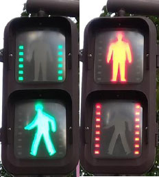 |
Fig. (1). Pedestrian traffic light with countdown in Japan. |
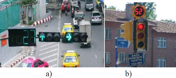 |
Fig. (2). Countdown traffic signals (number type; a) large size, b) medium size) [21]. |
Lum et al. [5] reported a before-and-after study in Singapore, where they evaluated the difference in drivers’ responses as they approached a signalized intersection installed with GSCD, a number-type countdown for vehicles (number type/large size). GSCDs effectively encouraged red-stopping actions under heavy traffic flows. Thus, they concluded that the longer-term performance of GSCDs would only encourage stopping but not curbing red violations. Huang et al. [6] evaluated the time-reminder strategies before amber in traffic lights of common signals, green flashing, and green countdown devices relative to red-light violence, and intersections with GSCDs showed lower red-light violations than those with common signal and green-signal flashing devices. Huang et al. [7] studied drivers’ stopping and traversing behavior during inter-green periods at eight intersections in Changchun, China, with and without GSCDs (number type/large size) and/or video surveillance (VS) during summer and winter. The author found that drivers are the most likely to stop at intersections having both GSCD and VS during phase transitions in summer, whereas, in winter, drivers have a high tendency to stop at intersections with either of the devices installed. Ma et al. [8] investigated the impacts of GSCDs based on field observations of critical driver- and vehicle-related parameters at two similar intersections with and without GSCD in Shanghai, China. The results show that installing GSCD can smoothen drivers’ responses to phase transitions and effectively prevent sudden changes in speeds. However, GSCD can adversely increase the possibility of collisions due to the significantly increased speeds of vehicles when approaching the amber time.
Considering the effect of RSCDs on vehicle behavior at signalized intersections, Yilmaz et al. [9] surveyed Kayseri, Turkey, in 2004–2005 and compared drivers’ behavior at traffic signal intersections with and without RSCDs (number type/middle size). They found that RSCDs can reduce startup delay; however, they increase the rate of early starts, where drivers start to move vehicles before the green phase. Limanond et al. [10] explored the impact of countdown signals at various stages of signal cycles in Bangkok. The presence of countdown signals at an intersection reduced the startup loss time at the beginning of the green phase by 22% and the number of red-light violations at the beginning of the red phase by 50%. Furthermore, more than half of the local drivers reported that the countdown relieve them of the frustration caused by stopping for an uncertain time during the red phase. The public-opinion survey showed that most local drivers were satisfied with the system. Islam et al. [11] predicted the effect of RSCD on the headway of the first vehicle waiting on a red signal. Krukowicz et al. [12] confirmed from implementation at three intersections in Plock (Poland) that RSCD increase the number of aggressive drive. Papaioannou et al. [13] indicated that the percentage of the violations of the early start for the signal with RSCD was observed to 24% from field observations at two intersections in northern Greece.
Chiou et al. [14] investigated the effects of GSCD and RSCD (number type/middle size) on drivers’ behavior by comparing several observation periods in Taiwan. The results show, that although RSCD significantly reduced the early start rates of leading vehicles in various waiting areas, the rates returned to their initial values in no distant time, suggesting that RSCD does not significantly improve intersection safety over long periods. However, the authors did not analyze the time of early start; thus, it is unclear how much time of early start was observed. However, RSCD effectively reduced startup delay four and half months after RSCD installation. RSCD is less controversial and more beneficial than GSCD. Jatoth et al. [15] evaluated the performance of traffic operations with and without a signal countdown timer at two signalized intersections (number type/middle size) in Hyderabad city, India. They observed a significant increase in the road capacity when the countdown was active. The average approaching speed of vehicles and red-light violations were observed to vary with the conditions of signal countdown timers. The signal countdown device effectively enhanced the traffic safety and operational performance of signalized intersections. Li et al. [16] proposed a method based on digital image processing for measuring drivers’ perception–reaction times (PRTs) relative to the startup loss time. The detection of the vehicle start was based on the frame difference. Comparative analysis of drivers’ PRTs with and without RSCD (number type/middle size) in Beijing, China, showed that the drivers’ PRTs decreased from 2.12 to 1.48 s with RSCD. However, the authors did not consider early start behavior.
Countdown traffic lights and vehicle behavior have also been analyzed in a simulation environment. Islam et al. [17] investigated drivers’ responses in the presence of RSCD. Driver behavior was observed for 67 Oregon drivers in a simulated environment. RSCD was predicted to reduce the first vehicle headway by 0.72 s and improve intersection efficiency by reducing the startup loss time. Kim et al. [18] analyzed how RSCD helps drivers decide how to control vehicle idling and investigated its environmental benefits by developing a mobility simulator. They observed 10.9% and 56.8% reductions in greenhouse gas emissions for stationary and idling vehicles, respectively, indicating that RSCD can effectively reduce greenhouse gas emissions.
Based on the above-cited studies, the evaluation of the safety of countdown traffic signals varies with country or region. Road conditions, such as road congestion, cars, bike, and pedestrian contamination, and installation intervals of traffic lights, differ among countries. Therefore, since the degree of traffic accidents varies, accident reduction after the installation of countdown traffic signals may also be different.
Compared to GSCD, RSCD has been extensively evaluated. RSCD can reduce startup delay and increase the capacity and control idling to reduce exhaust gas. However, it promotes early starts. Chiou et al. [14] and Yilmaz et al. [9] have analyzed early starts due to RSCD. Chiou et al. [14] reported that the early start rate increases when RSCD is installed, but they did not verify the quickness of early start time. Yilmaz et al. [9] verified the early start time in the signal intersections with RSCD and reported that the rate of early starts is approximately −2 to −1 s before the signal switches to green. On the other hand, in our study below, the early starts at signalized intersections without RSCD occurs much earlier than that with RSCD. Thus, RSCD also suppresses intensity of early start. Although RSCD is generally well-accepted, according to previous studies, and its relationship with accidents has been rarely reported, considering safety, it promotes early starts. Therefore, while maintaining the good effects of RSCD, forms of RSCD that can suppress early starts as much as possible need to be developed. To suppress early starts using RSCD, the start timing for drivers can be made slightly difficult to understand by altering the general provision form in which the countdown number is displayed every second. For example, signals, such as red signals, fixed numbers, or dots, as seen on pedestrian traffic lights, can be displayed before the green phase.
In Japan, countdown traffic lights for vehicles have not been commercialized. We have developed vehicle traffic lights that can provide countdown information in the green and red phases with various display forms and examined drivers’ startup behavior, such as early starts, under the countdown information. The early starts can be classified into ER and PS in our study mentioned in chapter 1. In our previous study (Tomomatsu et al. [1]), we conducted an experiment and found that ER is likely to occur in the RC traffic light of any display forms, but PS was not observed in the experiment with no countdown(NC). From our subsequent research, it was revealed that the frequent occurrence of ER in RC experiment was attributed to microscopic movements within 1 s just before the green phase. No ER was observed when no countdown was installed in the experiment because the intersection used in the experiment had no traffic lights or vehicles in the crossing direction; it only had traffic lights in the running direction. In this regard, Fujita & Kawabata [19] (in Japanese) conducted a survey at actual signalized intersections without countdown and a basic research with insufficient data and microscopic analysis without statistical examination.
Therefore, in this study, we further conducted the actual signalized intersection surveys without countdown and the experiments with RC traffic lights of various display forms. Then, we analyze the microscopic characteristics for vehicle startup behavior within 1 s before the green phase in 10 countdown display forms, perform various statistical analysis as mentioned in the end of Chapter 1.
3. INTERSECTION SURVEY AND EXPERIMENT
3.1. Intersection Survey
To analyze the startup behavior of vehicles, 12 signalized intersections in Japan were selected and observed. The survey was conducted at eight intersections in 2018 and then four other intersections in 2020 to improve the reliability of the data. The outlines of the 2018 and 2020 surveys are listed in Table 1. The survey points were selected so that the time for the red signal and the total red time, which may be related to the difference in startup behavior, were well balanced. The distance between the stop lines in the running direction at an intersection is considered the scale of the intersection.
All surveys were conducted at 16:00 on weekdays when it was not raining. The movement of a vehicle from a stop to a start at a traffic light was filmed using a video camera installed right next to the stopped vehicle for 30 signal cycles at each intersection. The image taken by the video camera was advanced frame by frame for 1/30 s, and the moment when the tire rotates by 1° or more due to the enlargement of the image is considered the startup reaction. We used the startup reaction time (SRT) defined below. In other words, the time when the signal turns green is defined as the reference 0 s, and the difference between the reference time and the time when the startup reaction is observed is defined as SRT. Additionally, when the tire of the vehicle starts moving later than the reference time, SRT is defined as positive, and when it moves earlier than the reference time, SRT is negative. The negative SRT is also defined as the early reaction time (ERT) when a vehicle performs ER.
If the first vehicle is big, like trucks, or if a vehicle on the crossing road remains at the intersection, even when the traffic light turns green in the running direction (these are residual vehicles), the startup behavior may be affected. Thus, we excluded these observation data because they are unsuitable for matching the conditions as much as possible compared with experimental data. Excluding these data, the 2018 survey acquired 132 data at 8 intersections, and the 2020 survey acquired 103 data at 4 intersections, totaling 235 survey data.
3.2. Equivalence of Intersection Survey Data over two Periods
To verify the equivalence of SRT in the 2018 and 2020 survey data, the distributions of SRT were compared, and the difference in the mean values was evaluated. Fig. (3) shows the distribution of SRTs for both surveys. In both cases, the frequency of SRT from 3 to 0 s (in the maximum value for each class) is the highest. The negative SRT data before the green phase is not remarkable, but distributions are similar. In the microscopic startup behavior of − 1 to 0 s, there was one dataset in 2018 and six datasets in 2020. However, as aforementioned, before eliminating the case where there are residual vehicles in the crossing direction, 5 and 7 cases in 2018 and 2020, respectively, show almost the same tendency.
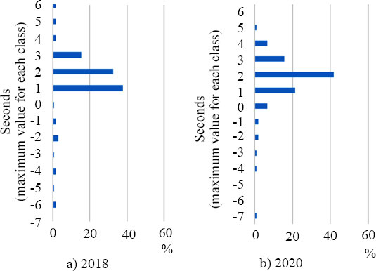 |
Fig. (3). Histograms of startup reaction time in each survey. |
| Intersection Name | Direction | Survey Date | Number of Valid Data (vehs) |
Cycle Length (s) |
Red Phase Time(s) | Omnidirectional Red Phase Time(s) | Stop Line Distance (m) |
|---|---|---|---|---|---|---|---|
| 1.Fukiage ramp north | W→E | 2018/10/26 | 27 | 140 | 47 | 3 | 28 |
| 2.Hanada Park North | W→E | 2018/10/24 | 23 | 140 | 56 | 3 | 29 |
| 3.Fukiage Park North | W→E | 2018/10/19 | 18 | 140 | 72 | 3 | 28 |
| 4.Nakamichi | S→N | 2018/11/7 | 5 | 140 | 95 | 3 | 54 |
| 5.Hirokojiaoi | W→E | 2018/11/13 | 15 | 140 | 71 | 5 | 60 |
| 6.Toshincho | S→N | 2018/10/29 | 7 | 140 | 94 | 5 | 57 |
| 7.Aoi-cho West | S→N | 2018/10/22 | 18 | 140 | 100 | 5 | 55 |
| 8.Tokodori 2 | E→W | 2018/11/2 | 19 | 160 | 100 | 5 | 72 |
| 9.Arahata | E→W | 2020/12/15 | 29 | 160 | 53 | 3 | 38 |
| 10.Tokodori 1 | N→S | 2020/12/16 | 28 | 160 | 69 | 3 | 40 |
| 11.Maruta-cho | S→N | 2020/12/23 | 26 | 160 | 93 | 5 | 47 |
| 12.Koromo-cho | S→N | 2020/11/6 | 20 | 150 | 101 | 5 | 50 |
Table 2 lists the difference between the averagevalues of both data. Since homoscedasticity tests with a significance level of 5% for both data (dispersion rate: 1.243; P-value: 0.125) did not reject the homoscedasticity, the table shows the t-test results when the population variance is homoscedasticity. There is no significant difference between the results of the surveys. Therefore, the results obtained from both surveys are similar. In other words, in the 2018 survey, the reliability was poor because there was a little microscopic data on SRT, but the same results were obtained even when the survey year and location were changed. Therefore, the distribution and probability of occurrence of microscopic data at actual intersections in Japan are reliable. In subsequent analysis, the data from both periods will be integrated and used.
Table 2. The t-test of both surveys.
| - | 2018 | 2020 |
| Average | 0.958 | 1.159 |
| Variance | 3.248 | 2.612 |
| Number of observations | 132 | 103 |
| Degree of freedom | 233 | - |
| t value | -0.89 | - |
| P-value on both sides | 0.375 | - |
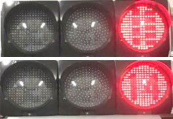 |
Fig. (4). Countdown traffic light used in experiment. |
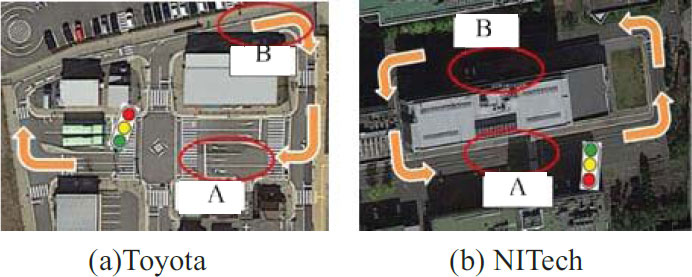 |
Fig. (5a,b). Experiment course. |
3.3. Outline of Experiments on Countdown Traffic Lights
Since countdown traffic lights are not yet used on roads in Japan, we conducted experiments using two simulated roads with traffic lights and the countdown information developed in our laboratory (Fig. 4) [19]. The experiments were conducted for four days at the Toyota Safety Drive Learning Center (Toyota) on December 14, 22, and 24, 2015, and at Nagoya Institute of Technology (NITech) on July 15, 2017. The experimental courses are shown in Fig. (5), and the experimental conditions are shown in Fig. (6). In both experiments, the countdown traffic light was installed at a position approximately 30 m ahead of the stop line, in the front right direction in the traveling direction of the experimental vehicle, and the height of the signal lamp was approximately 2 m. The total number of subjects in the entire experiment was 51 (28 males and 23 females): 16 in their 20s, 18 in their 30-40s, 15 in their 50-60s, and 2 in their 70s or older.
Three vehicles ran in the direction of the arrow in a vertical row of three vehicles on a running course with a countdown traffic light and stopped and started by waiting for a signal at point A. In addition, the order of running was rearranged at point B every lap, and the signal form was changed every six laps. However, for each signal form, the order of running was evenly rearranged so that the first, second, and third vehicles could be experienced twice per person. The order of the signal forms for a driver to be experienced was set randomly. In addition, the waiting time at the traffic light was set randomly within the range of 5–50 s. The flow and rules of the experiments at Toyota and NITech were the same, but the eight signal forms were used at Toyota (Table 3), whereas six forms were used at NITech, including four forms (NC, 3sRed, 2sRed, and 1sNum) in Table 3 and two forms (5sDot and 2sDot) in Fig. (7), which are defined as follows.
| Cowntdown Forms | Remaining Red Time(sec) | ||||||||||
| 10 | 9 | 8 | 7 | 6 | 5 | 4 | 3 | 2 | 1 | 0 | |
| NC |

|
|
|
|
|
|
|
|
|
|

|
| 5sRed | 10 | 9 | 8 | 7 | 6 | 5 |
|
|
|
|
|
| 5sNum | 10 | 9 | 8 | 7 | 6 | 5 | 5 | 5 | 5 | 5 |
|
| 3sRed | 10 | 9 | 8 | 7 | 6 | 5 | 4 | 3 |
|
|
|
| 3sNum | 10 | 9 | 8 | 7 | 6 | 5 | 4 | 3 | 3 | 3 |
|
| 2sRed | 10 | 9 | 8 | 7 | 6 | 5 | 4 | 3 | 2 |
|
|
| 2snum | 10 | 9 | 8 | 7 | 6 | 5 | 4 | 3 | 2 | 2 |
|
| 1sNum | 10 | 9 | 8 | 7 | 6 | 5 | 4 | 3 | 2 | 1 |
|
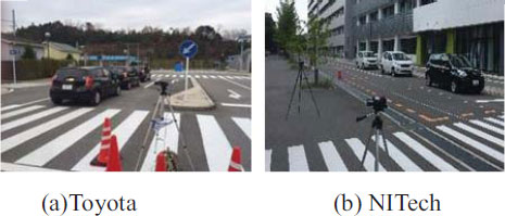 |
Fig. (6a,b). Experiment situation. |
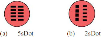 |
Fig. (7a,b). Signal forms (NITech Dot forms). |
NC is a form that does not display any countdown. Other forms indicate that a countdown is displayed until the remaining L seconds when the signal turns green. After the remaining L seconds, the LsRed (L = 2, 3, and 5 in the table) switches to the red signal and maintains it until the signal switches to green. Similarly, LsNum displays the last number that is fixed and continues after the countdown displays until L seconds. The 5sDot is a form in which the dots disappear one by one from the upper left every 5 s and turns green when all dots disappear. In the 2sDot form, the dots on the right side disappear one by one from the top every 2 s, and when all the five dots disappear, a top dot on the left side disappears and 5 dots appear on the right side again. Then, a dot on the right side disappears one by one every 2 s in the same way, and when all the dots on the left and right disappear, the signal turns green.
These signal forms in the red phase are devised to reduce the frustration during red waiting time by displaying the countdown, thereby promoting smoothing starts, suppressing early starts, and improving safety. Based on previous studies, since it is easy for a driver to understand the time for the signal to turn green and to induce early starts when the countdown is displayed numerically up to 1 s, display forms that slightly blur the signal switching timing are mostly employed.
In the experiments at Toyota and NITech, there was no traffic light in the crossing direction, and there was nothing for drivers to judge the traffic condition other than the traffic light in the direction of travel. Therefore, although early starts occurred in the surveys at actual signalized intersections in the previous section, no early start was observed in the case of NC. Therefore, NC data in this experiment could have startup behavior slightly different from that of other experiments and surveys in this study. Thus, we excluded NC data of the experiment in the following analysis.
As in the case of the intersection survey in Section 3.2, the equivalence of the data obtained from the experiments at Toyota and NITech was verified by evaluating the difference between the average values of SRTs. The assumption that there is no significant difference in each form was accepted at a 5% significance level. Based on these results, in the subsequent analysis of startup behavior, among the 747 datasets obtained in the experiment, 646 datasets (502 cases at Toyoda and 144 cases at NITech), excluding 101 data of NC, were analyzed. In addition, 235 datasets from the intersection survey were analyzed, making the total datasets to be 881. The experimental data are only the data in red phase countdown (RC) traffic light, which excludes the NC data. The survey data include only NC data.
At the end of the experiment, a post-questionnaire was conducted to evaluate each signal form. The subjects answered three evaluation items: “easy to grasp the start timing,” “start safety,” and “comfort waiting for a signal” at five evaluation levels (1: very bad; 2: bad; 3: normal; 4: good; 5: very good). Fig. (8) shows the average score of the subjects for each evaluation item, using the numbers of the five-level evaluations as points. Thirty-six and fifteen subjects participated in the questionnaire for the Toyota and NITech experiments, respectively, and the numbers were slightly reduced when the signal form was different for the two experiments. Therefore, the amount of data for each signal form was 51 for NC, 3sRed, 2sRed, and 1sRed, 36 for 5sRed, 5sNum, 3sNum, and 2sNum, and 15 for 5sDot and 2sDot.
As shown in Fig. (8), 1sRed and 2sRed were highly evaluated as “easy to grasp the start timing” and “comfort waiting for a signal.” On the other hand, the evaluation was a little worse for NC, and 5sRed, 5sNum, and 5sDot, in which the countdown stopped 5 s before the signal turned green. Based on this result, the driver feels that displaying the countdown until the signal turns green makes it easier to grasp the start timing and simultaneously reduces the stress of waiting for the red signal. Since NC did not have any early start in the experiment, many subjects probably answered that it was safe. Considering the signal form in RC, many drivers would also think that it is safer to display the countdown until 1 s before the signal turns green because it is easier to grasp the start timing in terms of “start safety.” In the next chapter, we analyze these points in detail based on actual vehicle behavior.
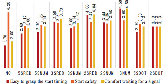 |
Fig. (8). Average score of the subjects in questionnaire. |
4. RESULTS AND DISCUSSION
Analysis of the startup and acceleration of the first vehicle considering microscopic behavior
Based on the images captured by the video camera installed in the intersection survey and experiment, we analyze the startup behavior regarding the startup reaction and acceleration characteristics of the first vehicle, considering the microscopic behavior. The early start considered here comprises ER and PS.
ER is defined as the startup reaction when the car starts moving until the traffic light turns green (see section 3. 1). However, based on the analysis herein, for vehicles that received countdown information, many minute movements were observed within 1 s before the signal turned green. The threshold value for ER is discussed in detail in the next section.
PS is defined as the premature start in which a vehicle passes the stop line before the signal turns green. Also, when a vehicle stops at a red signal and crosses the stop line, if the vehicle starts moving before the signal turns green, it is considered PS.
4.1. Microscopic Analysis of the Start Timing of the First Vehicle and Threshold of ER
Based on SRT of the first vehicle, the ease of grasping the start timing by the countdown is analyzed, considering the microscopic behavior 1 s before the signal switches to green. Fig. (9) shows the frequency distribution of SRT of the first vehicle based on the data of the 646 cases in the RC experiments and 132 cases in NC surveys described in Chapter 3. A large startup delay and large ER of −5 to −6 s were observed in the case of NC but not in RC. Thus, by displaying the countdown, variations in start timing and large ER can be suppressed.
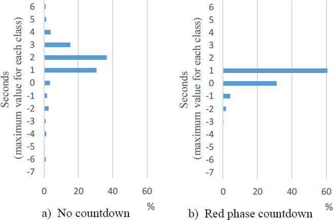 |
Fig. (9a,b). Histograms of startup reaction time in no count (NC) and red phase count (RC). |
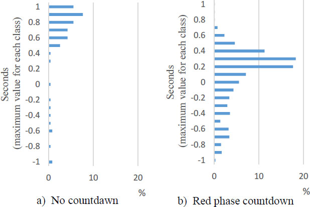 |
Fig. (10a,b). Microscopic analysis of startup reaction time in no countdown(NC) and red phase count(RC). |
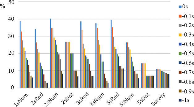 |
Fig. (11). Ratios of early reaction when the threshold value of early reaction in 0s to -1s. |
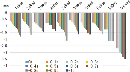 |
Fig. (12). Average early reaction times when the threshold value of early reaction is in 0s to -1s. |
| Threshold of Eraly Reaction | RC Experiment ER Rate | NC Survey ER Rate | Number of Samples | Pearson X2 | Fisher's Exact Test | |
|---|---|---|---|---|---|---|
| p value A | p value B | |||||
| 0 | 35.14 | 11.49 | 881 | 46.97*** | 0.0001*** | 1 |
| -0.5 | 17.03 | 9.79 | 881 | 7.048*** | 0.004*** | 0.998 |
| -0.6 | 15.48 | 9.36 | 881 | 5.541** | 0.012** | 0.994 |
| -0.7 | 11.76 | 8.51 | 881 | 1.879 | 0.104 | 0.935 |
| -0.8 | 9.13 | 8.51 | 881 | 0.082 | 0.446 | 0.657 |
| -1.2 | 5.11 | 7.23 | 881 | 1.454 | 0.912 | 0.149 |
| -1.3 | 4.33 | 7.23 | 881 | 2.989* | 0.968 | 0.063* |
| -1.4 | 4.18 | 7.23 | 881 | 3.388* | 0.975 | 0.051* |
| -1.5 | 3.56 | 7.23 | 881 | 5.366** | 0.991 | 0.019** |
On the other hand, in RC, the rate of SRT from −1 to 0 s is higher than that in NC. Thus, by displaying the countdown, the rate of startup reaction 1 s before the green phase increases. For more detailed analysis, Fig. (10) shows SRT from −1 to 1 s. There are small data around 0 s in NC, but most data are distributed in the range of 0 ± 1 s in RC. In particular, the ER rate from −1 to 0 s in RC is considerably higher than that in NC.
The rates of ER are shown in Fig. (11) when the threshold value of ER is in a 0.1 s decrement, less than 0 to −1.0 s. Until the threshold decreased below −1.0 s, the rate of ER for NC remained 11.06%–8.09%. In contrast, RC (all designs except 5sRed) with a threshold of less than −1.0 s showed an ER rate of 8% or less, which is below that of NC. The 2sRed form showed the lowest ER rates of 34% at a threshold of less than 0 s, 12.7% at a threshold of −0.5 s, 10.8% at −0.6 s, 7.8% at −0.7 s, and 2.9% at −1 s. At approximately −0.6 s, the ER rates of 2sRed and NC were comparable, and at −1.0 s, the rate of 2sRed decreased significantly to 1/3 of that of NC. Similarly, the ER rate of 5sDot reached 7.1% at a −0.4 s threshold. Thus, the change in startup behavior in RC was much higher than that in NC in the 1-s range before the green phase.
Considering the ER rate for each threshold, Table 4 lists the contingency table of non-ER and ER for RC and NC and the Pearson χ2 and Fisher accuracy tests. The ER rate of RC was significantly higher than that of NC when SRT ranged from 0 to less than −0.6 s, and there was no significant difference in the thresholds of −0.7 to −1.2. In contrast, the ER rate for NC was significantly higher than that for RC at thresholds of −1.3 or less. Therefore, ER occurred severally in RC at SRTs of 0 to −0.6 s and in NC at SRTs of −1.3 s.
Fig. (12) shows the average early reaction time, which is the average of SRTs at ER for each threshold and signal design. Notably, ERT is defined as SRT at ER. The average ERT of NC for each threshold was −3.4 to −2.7 s, but it was approximately −0.5 to −1.7 and −2.1 s for each signal form in RC. Most of these values are approximately half those of NC. The average ERT for RC was shorter than that for NC at all ER thresholds. On the other hand, in NC, ERT was fairly early because the driver could not predict the signal switching time and was irritated by the red signal and involuntarily performed ER.
Here, we consider the conditions for setting the ER thresholds in this study. In the following chapter, we analyze the difference in the startup behavior at ER and non-ER, and the ER threshold is very important. As a threshold for determining whether a value is ER, if the time the signal turns green is set to the reference value (0 s), the ER threshold is set to 0 s. However, in this study, we also considered the case where the ER threshold is set to less than −0.6 s for the following reasons regarding the behavioral characteristics of a driver.
i) From the analysis in Fig. (11), considering whether RC or NC has a smaller ER rate and is safer, the magnitude of both rates is inverted or the same for approximately −0.6 s before the signal turns green. ii) In RC, the driver intuitively predicts the signal switching time from the sense of rhythm as the countdown progresses and starts the starting operation. However, the ER from −0.6 to 0 s is considered an event that is likely to occur due to the delicate force adjustment of the accelerator work and the ambiguity of the senses, with almost no awareness of the driver making the early start movement. When the ER threshold is set to −0.6 s, it may be necessary to further discuss safety. However, herein, we analyzed the characteristics of vehicle startup microscopic behavior while comparing with two thresholds.
4.2. ERT Model for Signal Forms
Here, we conducted multiple regression analyses to analyze the ER characteristics that depend on the signal forms (including NC). This objective variable is the ERT of the thresholds less than 0 and −0.6 s in the previous section. Table 5 defines the explanatory variables used in all statistical models herein. The variables used in the ERT model include Nos.1 to 9 in Table 5, which are dummy variables of all signal forms. Table 6 lists the model results. We used 254 cases of ER at the threshold of 0 s and 122 cases of ER at −0.6 s from the 881 datasets in the previous section.
| No. | Explanatory Variable | Definition |
|---|---|---|
| 1 | 5sRed | A Dummy variable=1 for signal form 5sRed ; 0 otherwise |
| 2 | 5sNum | A Dummy variable=1 for signal form 5sNum ;0 otherwise |
| 3 | 3sRed | A Dummy variable=1 for signal form 3sRed ;0 otherwise |
| 4 | 3sNum | A Dummy variable=1 for signal form 3sNum ;0 otherwise |
| 5 | 2sRed | A Dummy variable=1 for signal form 2sRed ;0 otherwise |
| 6 | 2sNum | A Dummy variable=1 for signal form 2sNum ;0 otherwise |
| 7 | 1sNum | A Dummy variable=1 for signal form 1sNum ;0 otherwise |
| 8 | 5sDot | A Dummy variable=1 for signal form 5sDot ;0 otherwise |
| 9 | 2sDot | A Dummy variable=1 for signal form 2sDot ;0 otherwise |
| 10 | Nearest scale line distance (m) | Distance from the stop position of the vehicle head to the nearest scale line |
| 11 | RC experiment | A Dummy variable=1 if the data is obtained by the RC experiment; 0 otherwise |
| 12 | Distance to stop line (m) | Distance from the stop position of the vehicle head to the stop line(m) |
| 13 | Acceleration(m/s2) | Acceleration up to 3m after startup(m/s2) |
| Explanatory Variable | Threshold Less than 0s | Threshold Less than -0.6s | ||
|---|---|---|---|---|
| Estimated Value | t Value | Estimated Value | t Value | |
| Intercept | -2.588 | -14.87*** | -3.025 | -14.29*** |
| 2sRed | 2.108 | 9.10*** | 2.031 | 5.38*** |
| 3sNum | 2.054 | 8.34*** | 2.115 | 5.60*** |
| 1sNum | 1.968 | 8.65*** | 1.877 | 5.61*** |
| 3sRed | 1.890 | 8.35*** | 1.708 | 5.19*** |
| 2sNum | 1.871 | 7.73*** | 1.934 | 5.66*** |
| 5sRed | 1.860 | 7.62*** | 1.735 | 4.86*** |
| 5sNum | 1.839 | 6.79*** | 1.865 | 4.60*** |
| 2sDot | 1.790 | 4.92** | 2.090 | 4.41** |
| 5sDot | 1.320 | 2.72** | - | - |
| Adjusted degrees of freedom R2 | 0.320 | 0.369 | ||
| F Value | 12.73*** | 8.25*** | ||
| samples | 254 | 122 | ||
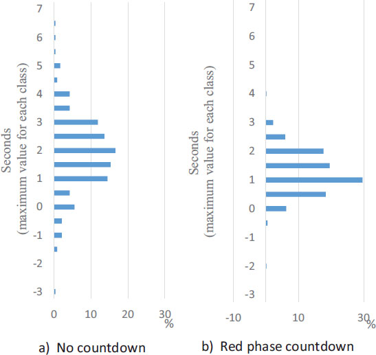 |
Fig. (13a,b). Histograms of distance from a vehicle head to stop line (no count(NC) and red phase count(RC)). |
From the ERT model, the dummy variables for most signal forms are significant. From the intercept, the ERT model at the −0.6-s threshold is smaller than that at the 0-s threshold by approximately 0.4 s because the models are limited to ER data of different thresholds. The ERT of NC is represented by this intercept, and the other variables are related to the ERT of each form of RC. ERT of RC is approximately 4 s slower than that of NC, as shown in Fig. (12). Considering each form with the 0-s threshold, the ERT of 2sRed is the slowest, and that of 3sNum and 1sN is slightly smaller, in that order. The difference of the order of forms is almost the same tendency for both threshold models.
4.3. Safety in PS
Here, we consider PS, in which a vehicle crosses the stop line before the signal turns green, and perform a comparative analysis. The data used include 646 cases in the RC experiment and 235 cases in the NC survey. Fig. (13) shows the frequency distribution of the distance from the stop position of the vehicle to the stop line in RC and NC. Although the distribution in NC is slightly wider than that in RC, both show the same trend in the stop position. The distance to the stop line is negative when the vehicle stops beyond the stop line, and in this case, any movement before the signal turns green is considered to be PS.
The rates of the PS of the signal forms in NC and RC (Fig. 14) are shown by two sets of bar graphs. The left bar set represents the rate of PS (at the 0-s threshold) to all data, and the right bar set shows the rate of PS (at the −0.6-s threshold, which is the same as the ER threshold obtained in the previous section). The average percentage of PS for the RC signal forms was approximately 6.5%, and all forms showed similar percentages. Based on the left bar set, the rate of PS in NC is 1.7%. The rates of PS for each signal form in RC are 4.17% and 4.90% for 3sNum and 2sRed, respectively, which are 1/7 or less of the ER rates (0-s threshold) but slightly higher than the rate of PS of NC. However, considering the right bar set of PS at the −0.6-s threshold, the rate of PS in NC is 0.85%. In RC, the rates of PS are 0%, 1.41%, 1.96%, and 2.04% for 5sDot, 5sRed, 2sRed, and 1sNum, respectively.
The rates of RC decreased further and the difference between NC and RC narrowed. This is because many vehicles in RC, which stop beyond the stop line, perform PS within 0 to −0.6 s, the same rate as the ER explained in the previous section. When also crossing the stop line, the start timing is microscopically ambiguous at around 0 s due to the countdown. In this study, we also performed a similar analysis excluding the stopping vehicles that crossed the stop line and obtained similar results with a threshold of −0. 6 s.
4.4. Acceleration Characteristics of the First Vehicle
In the RC experiment, scale lines were drawn at 1-m intervals before and after the stop line. The acceleration characteristics of the vehicle in the 1-m range immediately after the start were analyzed by obtaining the time from the stop position of the vehicle to the arrival of the nearest scale line (the nearest scale line arrival time). Similarly, in the NC survey, the nearest scale line arrival time was calculated assuming there were virtual scale lines at 1-m intervals before and after the stop line.
Table 7 lists the percentage of vehicles that reached the nearest scale line before the signal turned green relative to ER with thresholds less than 0 or −0.6 s. Fig. (15) shows the frequency distribution of the distance from the vehicle stop position to the nearest scale line. There is no significant difference between the distance distributions to the nearest scale line of the vehicle for NC and RC. In addition, there are data up to 1.2 m because the vehicle data very close to the scale line could not sufficiently measure the acceleration; thus, the scale line ahead was used. NC with a low ER rate reached the nearest scale line before the green phase more than RC (Table 7). This is because the rate of ER from −1 to 0 s in RC was high; thus, even if the vehicle made an ER, the time until the green phase would be very short, and the signal would be green already when the vehicle in RC would reach the nearest scale line. Therefore, the rate of reaching the nearest scale line before the green in RC decreased.
Tables 8-11 list the construction results of the model used in the multiple regression analyses with the nearest scale line arrival time as the objective variables. The explanatory variables used here include dummy variables for signal forms: Nearest scale line distance and Experiment dummy (No.1 to 11 in Table 5). The models were constructed using 881 datasets, including the 646 datasets of RC and 235 datasets of NC. The model at ER uses 254 data with a threshold of less than 0 s, the model at non-ER uses 627 data with a threshold of 0 s or more (or the model at ER uses 122 data with a threshold of less than −0.6 s, and the model at non-ER uses 759 data over a threshold of −0.6 s).
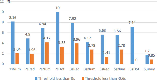 |
Fig. (14). Rates of premature start in each signal form and threshold value when the threshold value of early reaction is in 0s and -0.6s. |
| - | Number of Samples | Percentage of Early Reaction by Threshold |
Number of Cases that Reached the nearEst Scale Line Before the Signal Switches Green | Percentage of Reaching the Nearest scaLe Line Before the Signal sWitches Green | Average Distance to the Nearest Scale Line | |
|---|---|---|---|---|---|---|
|
0s |
-0.6s | |||||
| NC survey | 235 | 11.0% | 9.4% | 10 | 4.26% | 0.64 |
| RC experiment | 646 | 35.1% | 15.5% | 24 | 3.72% | 0.62 |
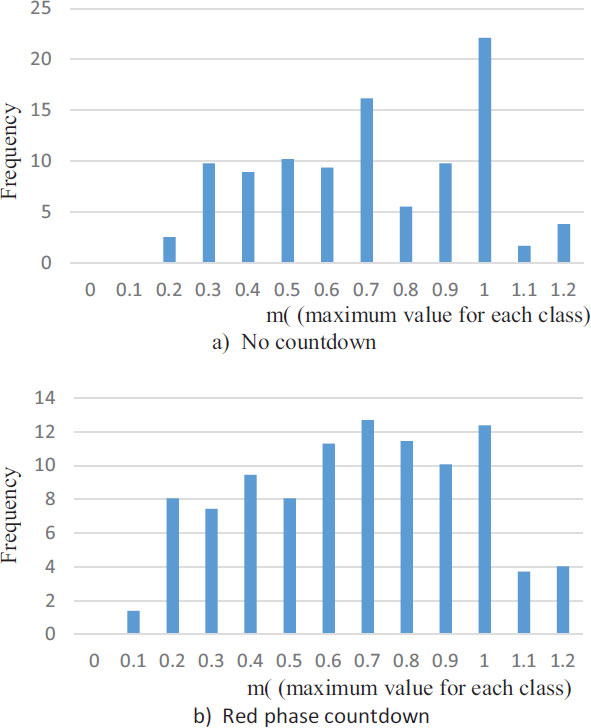 |
Fig. (15a,b). Histograms of distance from a vehicle head to nearest scale line (NC and RC). |
| Explanatory Variable | Threshold Less than 0s | Threshold Less than -0.6s | ||
|---|---|---|---|---|
| Estimated Value | t Value | Estimated Value | t Value | |
| Intercept | -0.267 | -1.47 | -0.497 | -1.79* |
| Nearest scale line distance(m) | 0.788 | 4.59*** | 0.852 | 2.75*** |
| RC experiment | 0.547 | 3.43*** | 0.391 | 1.69* |
| Adjusted degrees of freedom R2 | 0.110 | 0.082 | ||
| F Value | 16.59*** | 5.32*** | ||
| Number of samples | 254 | 122 | ||
| Explanatory Variable | Threshold Less than 0s | Threshold Less than -0.6s | ||
|---|---|---|---|---|
| Estimated Value | t Value | Estimated Value | t Value | |
| Intercept | 2.168 | 32.13*** | 2.128 | 33.57*** |
| Nearest scale line distance(m) | 0.771 | 9.28*** | 0.777 | 10.27*** |
| RC experiment | -1.138 | -22.9*** | -1.210 | -25.47*** |
| Adjusted degrees of freedom R2 | 0.500 | 0.508 | ||
| F Value | 314.4*** | 390.3*** | ||
| Number of samples | 627 | 759 | ||
| Explanatory Variable | Threshold Less than 0s | |
|---|---|---|
| Estimated Value | t Value | |
| Intercept | -0.189 | -1.14 |
| Nearest scale line distance(m) | 0.823 | 4.68*** |
| 5sNum | 0.604 | 2.74*** |
| 5sRed | 0.510 | 2.60*** |
| 3sNum | 0.491 | 2.50** |
| 2sRed | 0.490 | 2.68*** |
| 2sNum | 0.428 | 2.21** |
| 1sNum | 0.421 | 2.34** |
| 3sRed | 0.350 | 1.96** |
| Adjusted degrees of freedom R2 | 0.093 | |
| F Value | 4.23*** | |
| Number of samples | 254 | |
| Explanatory Variable | Threshold Less than 0s | |
|---|---|---|
| Estimated Value | t Value | |
| Intercept | 2.163 | 31.9*** |
| Nearest scale line distance(m) | 0.778 | 9.31*** |
| 2sRed | -1.197 | -14.49*** |
| 5sRed | -1.179 | -11.99*** |
| 2sNum | -1.176 | -11.95*** |
| 5sNum | -1.168 | -12.92*** |
| 3sNum | -1.166 | -12.07*** |
| 1sNum | -1.139 | -13.24*** |
| 3sRed | -1.115 | -13.12*** |
| 2sDot | -0.962 | -7.30*** |
| 5sDot | -0.925 | -7.30*** |
| Adjusted degrees of freedom R2 | 0.507 | |
| F Value | 63.4*** | |
| Number of samples | 627 | |
From the NC–RC comparative model for drivers performing ER (Table 8), the coefficients of determination of both the models with the two thresholds were low. In both models, the RC experiment dummy was positive, and the nearest scale line arrival time was delayed by approximately 0.4–0.5 s compared to that of NC. Comparing the threshold values, the RC experiment dummy at −0.6-s threshold is slightly smaller than that at 0 s, and the difference between NC and RC is smaller. Similarly, based on the non-ER model (Table 9), the coefficients of determination of both the models with the two thresholds were high. RC arrives about 1 s earlier than NC, and the −0.6-s threshold reaches slightly earlier than the 0-s threshold. Based on these results, when the countdown is displayed, drivers easily adjust their acceleration, and the vehicles of ER start slower than usual (NC), but those of non-ER start faster than usual (NC).
Tables 10 and 11 compare the models for different signal forms. Considering the significant variables in Table 10, the partial regression coefficients of 5sNum, 5sRed, 3sNum, and 2sRed of the signal forms are 0.49 or higher, and the nearest scale line-arrival time is more than that of others. Similarly, in the non-ER model (Table 11), the coefficients of 2sRed, 5sRed, and 2sNum are −1.17 or higher, which is slightly higher than that of the other models.
2sDot and 5sDot do not differ significantly from NC in the ER model. Although they tend to reach 0.2 s later than other forms in non-ER, they are comparable to NC considering the slow start.
From the above results, 2sRed, 5sRed, and 5sNum are better when the safety at ER and the smoothness of non- ER are considered, although there is a slight difference between the forms. Moreover, when the countdown is displayed, in dot signal form, the nearest scale line arrival time is slightly large, and the characteristic at ER is similar to that in NC.
5. INTERSECTION OUTFLOW TIME
The advantages of introducing a countdown traffic light include the improvement of the number of cars handled at one green light and the alleviation of traffic congestion due to the increase in traffic capacity. To verify the effectiveness of the countdown traffic light in increasing traffic capacity, it is necessary to analyze the startup behavior not only for the leading vehicle but also for the second and subsequent vehicles. Generally, the head time of the third and subsequent vehicles converges to approximately 2 s in Japan(JSTE [20]). Thus, the number of outflow vehicles at one green traffic light increases if the outflow time of the third vehicle in the signal queue can be shortened by the countdown traffic signal. Therefore, by comparing the intersection outflow time (third-vehicle outflow time) up to the third vehicle in the intersection survey and experiment, we examine the effective countdown display and signal forms for increasing traffic capacity.
Fig. (16) shows the average outflow time of the first vehicle in the signal queue and the vehicle head time between the following vehicles. Among the 235 datasets acquired in the case of NC, 229, excluding 6 that did not have 3 or more vehicles in a signal queue, and 646 datasets of RC (a total of 875 datasets) were analyzed. Among them, 622 datasets (419 and 203 RC and NC cases, respectively), excluding 253 cases in which ER occurred in less than 0 s, (or 753 cases (546 and 207 cases of RC and NC, respectively), excluding 122 cases in which ER occurred in less than −0.6 s) were analyzed.
As shown in Fig. (16), by displaying the countdown, not only the lead vehicle but also the second and subsequent vehicles start faster. However, since the difference in the head time between RC and NC decreases as the car is behind, the head time of the third and subsequent vehicles in a signal queue converges to the same value regardless of NC or RC. Based on the results, analyzing the outflow times up to the third vehicle is effective in comparing the number of vehicles that can be handled by one green light.
Tables 12 and 13 list the model construction results based on the multiple regression analysis using the third vehicle outflow time as the objective variable, of which data are the same as those in Fig. (16). The explanatory variables used here are dummy variables for signal forms, including “RC experiment dummy,” “Distance to the stop line,” and “Acceleration” (Nos. 1–9 and 11–13 in Table 5).
Based on the NC–RC comparison model (Table 12), the third vehicle outflow time in NC is approximately 2.4 s lower than that in RC. Displaying the countdown increases the number of cars that can be handled at one green traffic light. Also, considering the difference in the ER thresholds, the outflow time with the −0.6-s threshold is faster than that with the 0-s threshold. However, the difference is 0.1 s. Therefore, the effect does not change so much with or without considering the threshold value when considering the outflow time of the third vehicle.
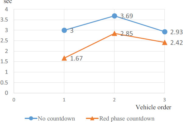 |
Fig. (16). Intersection outflow time to the third vehicle in no countdown (NC) and red phase countdown(RC). |
| Explanatory Variable | Threshold Less than 0s | Threshold Less than -0.6s | ||
|---|---|---|---|---|
| Estimated Value | t Value | Estimated Value | t Value | |
| Intercept | 10.600 | 60.16*** | 10.411 | 66.08*** |
| Distance to stop line (m) | 0.241 | 4.93*** | 0.263 | 5.86*** |
| Acceleration(m/s2) | -0.481 | -10.83*** | -0.435 | -11.66*** |
| RC experiment | -2.380 | -21.95*** | -2.460 | -24.31*** |
| Adjusted degrees of freedom R2 | 0.566 | 0.577 | ||
| F Value | 269.1*** | 340.0*** | ||
| Number of samples | 622 | 753 | ||
| Explanatory Variable | Threshold Less than 0s | |
|---|---|---|
| Estimated Value | t Value | |
| Intercept | 10.33 | 56.35*** |
| Distance to stop line (m) | 0.254 | 5.29*** |
| Acceleration(m/s2) | -0.394 | -8.23*** |
| 3sNum | -2.744 | -13.52*** |
| 2sRed | -2.618 | -15.31*** |
| 1sNum | -2.485 | -13.99*** |
| 2sNum | -2.484 | -12.08*** |
| 5sNum | -2.472 | -12.95*** |
| 5sRed | -2.420 | -11.81*** |
| 3sRed | -2.391 | -13.60*** |
| 2sDot | -1.494 | -5.45*** |
| 5sDot | -1.465 | -5.51*** |
| Adjusted degrees of freedom R2 | 0.587 | |
| F Value | 78.22*** | |
| Number of samples | 622 | |
From the signal form comparison model in Table 13, the third vehicle outflow time is faster in the order of 3sNum, 2sRed, and 1sNum in all the signal forms, although the difference is small. Also, in the Dot-type form, the third vehicle outflow time is approximately 1.5 s faster than that of NC, but it is about 1 s slower than that of other forms.
6. SUMMARY OF SIGNAL FORMS
Table 14 summarizes the analysis results of all 10 types of countdown signal forms (including NC) in this study. The numbers in the table are the aggregated values for each signal form obtained from analyses related to each evaluation item or the regression coefficient of the dummy variable of the models and are arranged in descending order from the one with the highest effect in each evaluation item.
For “start safety” in the questionnaire, NC showed the highest points of 4.2, followed by 1sNum and 2sRed with approximately 3.5 points. The rates of NC and 5sDot in the “ER rate” and “PS rate” for both threshold values are very small, and the rankings are very high. However, in the “Average ER time,” NC and 5sDts have considerably lower values (−2.58 s or less), and the ranking is exactly the opposite. Next, considering the “comfort waiting for a signal” and “easy to grasp the start timing” in the questionnaire, 1sNum showed the highest points of 4.5, followed by 2sRed, 3sRed, and 2sNum (3.5 points), but NC was poorly evaluated with an average score of 2 or less.
Next, for the microscopic startup behavior, that is “Nearest scale line arrival time at ER,” 5sNum, 5sRed, 3sNum, and 2sRed started significantly slower than NC at ER. From “Nearest scale line arrival time at non-ER,” 2sRed, 5sRed, and 2sNum started 1.17 s or earlier than NC at non-ER. 3sNum, 2sRed, 1sNum, and 2sNum were about 2.5 s faster than NC considering the “third vehicle outflow time.”
To understand these analysis results, Table 15 lists the total points in each form by scoring each evaluation item of the 11 columns of Table 14 using the ranking of the top 5 places. That is, the form at the top of each item in Table 14 is set to 5 points, the second to 4 points, down to the 5th, which is set to 1 point, and the subsequent ones are set to 0 points. The total score is the sum of all the items in each form, and the forms are arranged in descending order. In Table 15, there are three score calculations in the top 5th mentioned above and two other calculations mentioned below. The “0-s threshold” in the top 5 of Table 15 totals all items, except for the fifth and sixth columns for ER and PS with the −0.6-s threshold. For the “−0.6-s threshold,” all items., except for the second and third columns of the 0-s threshold, are aggregated in the same way. For “Three items” in the top 5, the columns of the “PS rate/threshold 0 s,” “Comfort waiting for a signal,” and “Third vehicle outflow time” are summed, which are important when considering the effect of the red signal countdown.
The three score calculations in the top 5 rankings result in almost the same form order. Even when considering the difference in the thresholds, the top four are the same, and after that, they vary slightly, although there are some changes. From the “0-s threshold” in the top 5, 2sRed was the highest, and 2sRed also showed high scores in many evaluation items in Table 14, followed by 1sNum, 3sNum, NC, and 5sNum, which displayed the countdown numerically. 2sRed was the highest because it is easy to grasp the timing by counting down to 2 s, but the switching timing is slightly blurred by waiting for 1 s with the red signal. Therefore, both the quick start and the suppressing of ER and PS are confirmed. 1sNum is easily understood as it displays the time numerically up to 1 s, and since there is less frustration during the red phase, the time of startup is good, and the average ER time is short. However, it is inferior to 2sRed in that “PS rate/threshold 0s,” including vehicles crossing the stop line and performing the early reaction from −0.6 to 0 s, increases slightly. Since 3sNum is also expressed by numbers, it is easy to understand, but the overall balance is improved because it is a little difficult to grasp the timing compared to 1sNum and 2sNum.
5sDot is close to NC in Table 14; for example, the quickness of startup (the rightmost 3 columns in Table 14) of 5sDot is lower than that of other forms, and the ER and
| Ran- King |
ER Rate (Threshold 0s) |
PS Rate (Threshold 0s) |
Start Safety (Questionnaire) |
ER Rate (Threshold -0.6s) |
PS Rate (Threshold -0.6s) |
Average ER Time |
Nearest Scale Line arrival Time at ER |
Comfort Waiting for a Signal (Questionnaire) | Easy to Grasp Start Timing (Questionnaire) | Nearesr Scale Line Arrival Time at non-ER |
Third Vehicle Outflow Time | |||||||||||
|---|---|---|---|---|---|---|---|---|---|---|---|---|---|---|---|---|---|---|---|---|---|---|
| 1 | NC | 11.1 | NC | 1.7 | NC | 4.2 | 5sDot | 7.1 | 5sDot | 0.00 | 2sRed | -0.48 | 5sNum | 0.604 | 1sNum | 4.50 | 1sNum | 4.50 | 2sRed | -1.20 | 3sNum | -2.74 |
| 2 | 5sDot | 14.3 | 3sNum | 4.2 | 1sNum | 3.6 | NC | 9.4 | NC | 0.85 | 3sNum | -0.53 | 5sRed | 0.510 | 2sRed | 4.04 | 2sRed | 4.00 | 5sRed | -1.18 | 2sRed | -2.62 |
| 3 | 5sNum | 26.4 | 2sRed | 4.9 | 2sRed | 3.5 | 2sRed | 10.8 | 5sRed | 1.41 | 1sNum | -0.62 | 3sNum | 0.491 | 3sRed | 3.73 | 3sRed | 3.50 | 2sNum | -1.18 | 1sNum | -2.49 |
| 4 | 2sDot | 26.7 | 5sNum | 5.6 | 3sRed | 3.4 | 5sNum | 12.5 | 2sRed | 1.96 | 3sRed | -0.70 | 2sRed | 0.490 | 2sNum | 3.58 | 2sNum | 3.44 | 5sNum | -1.17 | 2sNum | -2.48 |
| 5 | 2sRed | 34.3 | 5sRed | 5.6 | 2sNum | 3.4 | 3sNum | 15.3 | 1sNum | 2.04 | 2sNum | -0.72 | 2sNum | 0.428 | 3sNum | 3.42 | 2sDot | 3.13 | 3sNum | -1.17 | 5sNum | -2.47 |
| 6 | 3sNum | 37.5 | 2sNum | 6.9 | 5sDot | 3.3 | 1sNum | 16.3 | 3sNum | 2.78 | 5sRed | -0.73 | 1sNum | 0.421 | 5sNum | 3.14 | 3sNum | 3.00 | 1sNum | -1.14 | 5sRed | -2.42 |
| 7 | 3sRed | 38.6 | 5sDot | 7.1 | 5sNum | 3.3 | 3sRed | 16.8 | 5sNum | 2.78 | 5sNum | -0.75 | 3sRed | 0.350 | 5sDot | 3.13 | 5sNum | 2.70 | 3sRed | -1.12 | 3sRed | -2.39 |
| 8 | 1sNum | 38.8 | 3sRed | 7.9 | 5sRed | 3.2 | 5sRed | 18.3 | 2sDot | 3.33 | 2sDot | -0.80 | 2sDot | 0.000 | 2sDot | 3.13 | 5sDot | 2.70 | 2sDot | -0.96 | 2sDot | -1.49 |
| 9 | 5sRed | 39.4 | 1sNum | 8.2 | 3sNum | 3.1 | 2sDot | 20.0 | 3sRed | 3.96 | 5sDot | -1.27 | 5sDot | 0.000 | 5sRed | 3.00 | 5sRed | 2.60 | 5sDot | -0.93 | 5sDot | -1.47 |
| 10 | 2sNum | 40.3 | 2sDot | 10.0 | 2sDot | 3.1 | 2sNum | 20.8 | 2sNum | 4.17 | NC | -2.60 | NC | 0.000 | NC | 2.00 | NC | 1.70 | NC | 0.00 | NC | 0.00 |
| Score Calculation in the Top 5 | - | in the Top 10 | in the Top 3 | |||||||
|---|---|---|---|---|---|---|---|---|---|---|
| 0s Threshold | -0.6s Threshold | Three Items | - | 0s Threshold | 0s Threshold | |||||
| 2sRed | 31 | 2sRed | 32 | 2sRed | 11 | - | 2sRed | 76 | 2sRed | 14 |
| 1sNum | 20 | 1sNum | 21 | 3sNum | 10 | - | 1sNum | 60 | 1sNum | 10 |
| 3sNum | 18 | 3sNum | 15 | 1sNum | 8 | - | 3sNum | 60 | NC | 9 |
| NC | 15 | NC | 13 | NC | 5 | - | 5sNum | 55 | 3sNum | 8 |
| 5sNum | 13 | 2sNum | 12 | 2sNum | 4 | - | 2sNum | 53 | 5sNum | 4 |
| 2sNum | 12 | 5sRed | 11 | 3sRed | 3 | - | 3sRed | 49 | 5sRed | 4 |
| 3sRed | 10 | 3sRed | 10 | 5sNum | 3 | - | 5sRed | 43 | 3sRed | 2 |
| 5sRed | 9 | 5sDot | 10 | 5sRed | 1 | - | NC | 38 | 5sDot | 2 |
| 5sDot | 4 | 5sNum | 10 | 2sDot | 0 | - | 5sDot | 34 | 2sNum | 1 |
| 2sDot | 3 | 2sDot | 1 | 5sDot | 0 | - | 2sDot | 30 | 2sDot | 0 |
PS rate is highly ranked as that of NC. However, in Table 15, it is ranked lower than NC. This is because, in Table 14, the rankings of 5sDot in the “start safety” and “PS rate/threshold 0s” are low. However, the “PS rate: Threshold −0.6 s” of 5sDts is the highest. For the “comfort waiting for a signal” in Table 14, 5sDot has a similar ranking as NC, but the score (3) is higher than that of NC (2). Therefore, 5sDot may be a good display form to improve the “comfort waiting for a signal” in a similar operation to NC. On the other hand, 2sDot was ranked low in terms of “PS rate: Threshold−0.6s” and questionnaire evaluations in Table 14. This is because 2sDot is relatively easier to grasp the start timing as a dot disappears in 2 s, and the number of dots disappearing at the left and right differ. Hence, 2sDot is a little difficult for drivers to understand.
The rightmost two columns in Table 15 show the ranking (0-s threshold) in which the top 10th and 3rd place forms of each evaluation parameter in Table 14 are scored and arranged in the same manner as the top 5th place. The ranking of NC in Table 15 is greatly lowered in the scoring of the top 10 places, but the ranking of the other forms is almost the same as the score ranking of the 5th place. In the top three rankings in Table 15, the position of NC is slightly increased, but it is almost the same as the top 5 rankings. As shown in Table 14, NC is ranked high in terms of “start safety” (columns 2–6), except for the “average early reaction time,” but the quickness of startup (rightmost 3 columns) is the lowest. Then, NC lowers the top 10 rankings in Table 15, but the score is close to that of the upper and lower forms; thus, the ranking can easily change. Therefore, a comprehensive evaluation of the top 5th places is appropriate.
CONCLUSION
This study was based on a comparison of results obtained from driving experiments conducted at intersections of RC under limited and hypothetical conditions and from observational surveys of real intersections in NC. From the analysis, it was found that by displaying a countdown, there exists a micro period within 1 second in which drivers predict the signal changeover time and commit an ER as a driving error. Even an ER within this micro period would further reduce the PS rate because the signal would immediately turn green. However, even adjusting for the signal form, the PS rate increased by about 1% compared to the NC. Drivers in the RC tended to be less impatient because the comfort awareness rating score during the red light waiting time was two to three times higher than in the NC. In the acceleration analysis within the 1-meter range, predictive departure behavior was observed in RCs, in which drivers departed after understanding the exact time at which the signal would change to green.
The 2sRed and 3sNum forms minimized PS and improved the RC advantage. Namely, counting down until 2-3 seconds before the signal switched to green increased traffic capacity by reducing the departure delay, and suppressed ERs by slightly blurring the last few seconds of the signal. The common form, 1sNum, ranked high; dot forms such as 5sdot provided the closest operation to NC for waiting time comfort. However, the RC experiment in this study was conducted under limited road conditions, such as no vehicles or traffic signals in the crossing direction, and the results were obtained from 51 drivers, mostly young people, who participated in the experiment, so the results of this experiment may not be generalizable. The results may provide hints for the design of new countdown display forms that contribute to traffic safety by improving the promptness of starting at green light changeover while calming driver frustration during red time and controlling the PS ratio. In the future, it is necessary to proceed with verification of the effectiveness of starting behavior under various signal forms under more realistic conditions.
LIST OF ABBREVIATIONS
| PS | = Premature Start |
| ER | = Early Reaction |
| NC | = No Countdown |
| GSCDs | = Green-signal Countdown Devices |
| RSCDs | = Red-signal Countdown Devices |
CONSENT FOR PUBLICATION
Not applicable.
AVAILABILITY OF DATA AND MATERIALS
The data and supportive information are available within the article.
FUNDING
None.
CONFLICT OF INTEREST
The author declares no conflict of interest financial or otherwise.
ACKNOWLEDGEMENTS
I would like to acknowledge all the laboratory members involved in the experiments and analysis of this study. This manuscript has been published in the preprint of SSRN (doi.org/10.2139/ssrn.4137922).