All published articles of this journal are available on ScienceDirect.
Analysis of the Emission Reduction through Performance Improvement of Intersection and Network nearby Using Micro Simulation Program
Abstract
Introduction:
Palembang as one of the big cities in Indonesia is the capital city of South Sumatra Province. Congestion occurs at the main intersections of the city, one of which is Simpang Patal Pusri which has a long queue and delays in peak hour of 655 m and 490 seconds. The action performed to improve traffic performance and reduce the air pollution at this intersection was the underpass construction. This study discussed the importance of constructing an underpass together with improving geometric design and traffic management at the nearest intersections to obtain optimal results in addressing traffic problems and emissions reductions.
Methods:
To analyze the performance of traffic intersection and its network, Vissim simulation micro program and Program Moves were used to find out the emission values of Total Carbon, NOx and PM10 of the analyzed handling scenarios.
Results:
The results showed that the construction of an underpass accompanied by the improved geometric design and traffic management at the nearest intersection produced better intersection performance and emission reductions when compared to only underpass construction, where the average V/C decreased from 0.87 to 0.77, the average queue decreased from 290.3 m to 190.57 m, and the average delay decreased from 106.34 seconds to 85.07 seconds. The values of Total Carbon, NOx and PM10 also decreased significantly on all the roads in the study area.
Conclusion:
Based on the analysis, a scenario of the underpass construction is combined with geometric improvement and traffic management at the intersections which provides the best traffic performance and emissions reduction at either the intersections or road segments of the road network being studied.
1. INTRODUCTION
Palembang city with the number of population of 1.8 million people is the activity center of South Sumatra Province. The level of the existing vehicle movement in the city causes traffic congestion at city road networks and accumulation of vehicle exhaust emissions.
Palembang is a big city and construction of a flyover or underpass at a major intersection is necessary in order to overcome the traffic congestion and diminish the vehicle exhaust emissions at the intersection. In addition, Arliansyah et al. [1] state that a problem of network performance can be improved with the development of road network and bridges crossing Musi River that divides Palembang City. At the macro level, road network development should also be accompanied by traffic arrangement of the intersection. In 2014, the underpass was constructed at Patal Pusri intersection to overcome the congestion problems where the queue length and delay reached 655 m and 490 s.
Gastaldi et al. [2] point out that an intersection is a critical part of a road network because its performance affects the air quality in which a control type and an intersection geometric configuration can provide a significant effect on vehicle emission. The congestion on the intersection will decrease the air quality produced by vehicle emission. Lin et al. [3] conducted a study on optimizing intersections by algorithm that optimized PI (the comprehensive benefit value) and V/C for an Isolated Signalized Intersection to obtain the decreased emission and optimal delay. Chandan et al. [4] developed an algorithm for optimizing traffic lights connected to vehicles at isolated intersections which were then tested with the VISSIM program. However, if the intersection has reached its saturation condition, separating the main flow of traffic at the intersection by constructing an underpass or flyover is the best way.
Because of the emission reduction, the performance of an intersection and its road network nearby were affected by the performance of the nearest intersection which needed reviewing geometric design and performing a traffic management at the intersection and roads near the Underpass of Patal Pusri. This study analyzed the importance of constructing an underpass accompanied by geometric improvement and traffic management at nearby intersections and road networks to obtain optimal results in addressing traffic problems and emissions reductions.
2. PROGRAM OF TRAFFIC MICROSIMULATION AND EMISSION CALCULATION
Software of micro-simulation traffic is a program used to represent traffic conditions from real conditions that run like a simulated traffic situation. The simulation is carried out by embodying the driver behavior on the road and the road network enabling to measure the impact of travel patterns and changes that occur in the study area. This program has the ability to calculate delays, queue lengths, free flow speed, and service levels on both road and road networks. With this ability, the program is suitable for the use of analyzing traffic conditions in urban and suburban areas including analyzing from the types of intersections to the analysis of a study area. The micro-simulation program can show the impact of an environmental change occurring in the study area such as bottle neck, road geometry change, traffic flow diversion, or traffic light optimization. The analysis conducted on the micro-simulation program can be done either statically or dynamically. Dynamic analysis enables the simulation programs to accommodate the dynamics of traffic conditions at the site. Some studies on analyzing traffic performance using traffic micro-simulation programs have been reported [5-10].
MOVES is a calculation program to estimate the emission production in some area that simulated every second. The estimation is influenced by driving behaviour, delay, duration and vehicle characteristic measured by using VSP (Vehicle Specific Power) or STP (Scaled Tractive Power) method. The integration of traffic micro-simulation models and emission models have been reported [11-14]. Monitoring system of city carbon emission was carried out by Sun et al. [15] utilizing various kinds of equipment to gather the data of traffic flow, meteorological conditions, vehicular carbon emissions and driving characteristics on a typical road. The emission model Moves was used to analyze the traffic carbon emission. In addition, emission calculation using computer programs such as COPERT and ENVIVER were reported [16, 17].
3. METHODOLOGY
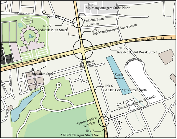
Fig. (1) shows the study location where the Patal Pusri intersection is adjacent to 2 intersections of Seduduk Putih and Taman Kenten.
The procedure method of the study is described as follows:
- Data collection of traffic flow, free flow speed and geometric condition of the network.
- Modeling of the existing traffic condition at Patal Pusri intersection and the two nearby intersections using simulation micro program of VISSIM.
- Calibration of the model.
- The development of traffic condition handling scenario is as follows:
- Existing traffic condition of the network without doing anything (Scenario 1).
- Constructing the underpass at Patal Pusri intersection without being combined with the traffic management at the nearest intersection (Scenario 2).
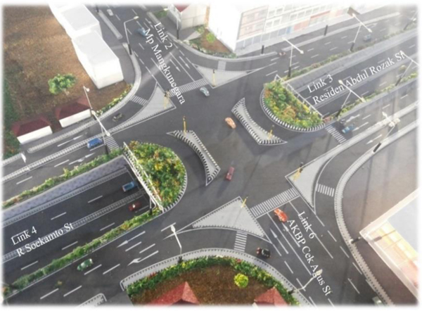
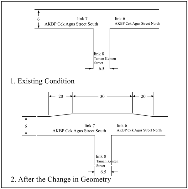
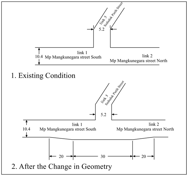
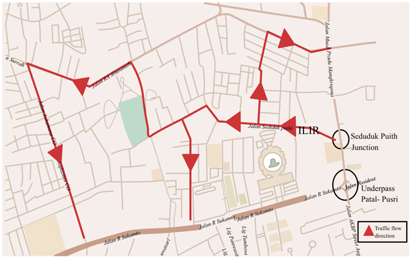
- Analyzing of intersection performance of Patal Pusri network with geometric change and traffic management at intersections near Underpass Patal-Pusri intersection (Scenario 3). Layout of Underpass Patal-Pusri, geometric change at Seduduk Putih intersection and Taman Kenten intersection are shown in Figs. (2, 3 and 4) consecutively. There is a 3.5 meter wide additional road with the length of 70 meters to avoid queue length and delay at peak hour. Traffic management mentioned in scenario 3 means diverting the vehicle exit from Seduduk Putih intersection to another road shown in Fig. (5).
- Evaluation of network performance and emission reduction was conducted for each developed scenario. Evaluation of network performance used queue length and delay while the emission parameters were total carbon, NOx and PM10. Moves Program was used to calculate the emission.
4. RESULT
4.1. Calibration of Model
In the VISSIM program, the calibration process was carried out by changing the minimum headway distance parameters, where the default value of minimum headway distance parameters in the VISSIM program was 0.5 m. The calibration process was conducted by changing the minimum value of headway distance with the following scheme:
- Minimum headway distance = 0.7 m.
- Minimum headway distance = 1.3 m.
Traffic volume data and free flow speed were used for the developed model calibration by comparing the traffic volume and free flow speed of modeling result with field value. It is very important to obtain a good result of calibration and validation of the micro-simulation model in order to have a reliable estimation of the emission produced by the vehicles. Table 1 shows the calibration criteria used in this study.
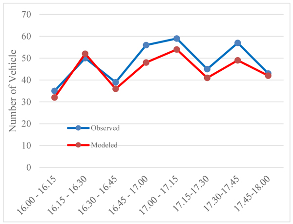
Table 2 and Fig. (6) show the comparison between the number of the modeled vehicles and the number of the observed vehicles starting from 4 p.m. to 6 p.m. representing the peak hours at Seduduk Putih intersection to MP Mangkunegara Street. Table 2 indicates that the optimum minimum headway distance value is optimally 0.7 with 92% similarity value. The value of similarity with default setting of minimum headway distance of 0.5 resulted in average model resemblance of 70%, while the minimal headway distance of 1.5 m only produced average model resemblance of 58%. It is obvious that the modeling volume approached the field volume and had values that met the calibration criteria shown in Table 1.
| No | Criteria and Measurement | Calibration Accepted Target |
|---|---|---|
| 1 | Modeled number of vehicle hourly flow vs. observed number of vehicle flow | 85% |
| 2 | Modeled speed vs. observed speed | 85% |
| Time | Observed | Modeled | Similarity (%) |
|---|---|---|---|
| 16.00 - 16.15 | 35 | 32 | 91% |
| 16.15 - 16.30 | 50 | 52 | 104% |
| 16.30 - 16.45 | 39 | 36 | 92% |
| 16.45 - 17.00 | 56 | 48 | 86% |
| 17.00 - 17.15 | 59 | 54 | 92% |
| 17.15 - 17.30 | 45 | 41 | 91% |
| 17.30 - 17.45 | 57 | 49 | 86% |
| 17.45 - 18.00 | 43 | 42 | 98% |
| Average similarity | 92% | ||
Table 3 and Fig. (7) show that the calibration of free flow speed also indicates that the model reached 96% of the average similarity. The average similarity means that the created model represented 96% similarity of free flow speed at the real condition.
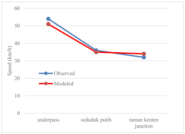
The calibration result shown in Tables 2 and 3 indicate that the model has already reflected the real condition which means the simulation model is ready for use in the analyses.
| Location | Modeled Speed (Km/H) | Observed Speed (Km/H) | Similarity |
|---|---|---|---|
| Underpass | 52 | 55 | 95% |
| Seduduk Putih | 33 | 36 | 92% |
| Taman Kenten | 32 | 31 | 103% |
| Average | 96% | ||
4.2. Network Performance
Evaluation of network performance was conducted for the three developed scenarios. Table 4 shows the Volume per Capacity ratio (V/C), delay and the queue length of all intersections of each developed scenario.
Table 4 illustrates that the existing condition of Simpang Patal Pusri was overloaded and saturated by the traffic. Compared with the second scenario, the V/C ratio decreased less than the first one but the amount was still near the full capacity indicating that the second scenario did not give an impactful result. While the third scenario shows the lowest V/C ratio, where it decreased 56% compared to the existing condition. It was the same as those of Taman Kenten Intersection and Seduduk Putih Intersection where the V/C ratio decreased as much as 68% at both intersections.
| No | Condition | Intersection | V/C | Maximum Queue Length (m) | Delay (s) |
|---|---|---|---|---|---|
| 1 | Existing (Scenario 1) |
Patal Pusri | 1.40 | 797.00 | 498.00 |
| Taman Kenten | 1.10 | 504.72 | 135.77 | ||
| Seduduk Putih | 1.16 | 211.18 | 184.68 | ||
| 2 | Underpass (Scenario 2) |
Patal Pusri | 0.96 | 423.00 | 120.00 |
| Taman Kenten | 0.83 | 256.08 | 89.02 | ||
| Seduduk Putih | 0.82 | 191.68 | 130.00 | ||
| 3 | Underpass + Traffic Management (Scenario 3) | Patal Pusri | 0.81 | 200.00 | 84.00 |
| Taman Kenten | 0.75 | 78.21 | 76.15 | ||
| Seduduk Putih | 0.74 | 26.75 | 76.4 |
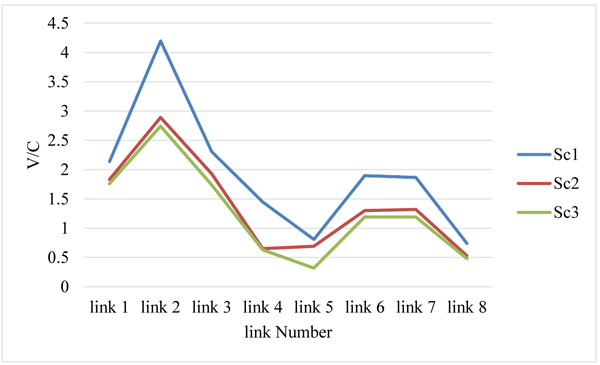
Based on Table 4 the existing condition of Patal Pusri intersection had a long queue of 797 meters and a delay of 498 seconds. The second scenario shows when an underpass was built, it would reduce the queue length and delay. The third scenario shows the best result that reduced maximum queue length for 33% and decreased the delay until 42% compared to the existing condition. Fig. (8) shows that the underpass construction combined with geometric improvements and traffic management at the nearest intersection could improve the performance of the studied roads on the road network. It is clear that constructing an underpass combined with management route of traffic at the intersection close to the underpass is the best scenario for having the best network service.
4.3. Integration VISSIM to MOVES Program
The emission was estimated using MOVES (Motor Vehicle Movement) by which a weighted average of emission was calculated using an operating mode. The exhaust emission was operated using VSP (Vehicle Specific Power) or STP (Scaled Tractive Power). Both VSP and STP were calculated based on a vehicle’s speed and acceleration, but they were different in how they were scaled. The formula of VSP and STP is given in equations (1) and (2) as follows:
 |
(1) |
 |
(2) |
where VSP is the Vehicle Specific Power (kw/ton), STP the Scaled Tractive Power (kw/ton), M is mass of each vehicle (metric tons), A is term of rolling (kw-s/m), B is term of rotating (kw-s2/m2), C is term of the aerodynamic (kw- s3/m3), is the fix vehicle speed (m/s), is the dynamic of acceleration (m/s2), is the gravity force (m/s2), is the road grade angle, and f is the mass factor for vehicle.
Hatem et al. [18] analyzed emissions on road segments resulted from the vehicle traffic using the VISSIM program that was integrated with the MOVES program with an analysis of every second of the rush hour condition. They found out that the vehicle emission calculations derived from the integration of Vissim and Moves programs provided better results. Xiaodan et al. [19] state that estimating transport network emissions in Monte Carlo used a Vissim program integrated with MOVES.
4.4. Result of Vehicle Emission Calculation
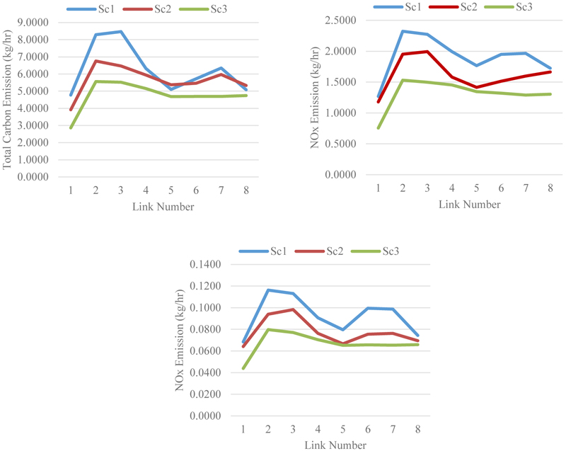
Tables 5 and Table 6 show the results of comparison of CO, NOx and PM10 using Moves program for the three analyzed scenarios. It shows that the three types of emission decreased in Scenario 2 (Sc2) and Scenario 3 (Sc3). Analyses of variance for the data in Table 6 yields F value as shown in Table 7 while Table 8 shows the P value comparison among scenarios.
| Source type | Link number |
Total Carbon Emissions (kg/hr) |
NOx Emissions (kg/hr) |
PM10 Emissions (kg/hr) |
||||||
|---|---|---|---|---|---|---|---|---|---|---|
| Sc1 | Sc2 | Sc3 | Sc1 | Sc2 | Sc3 | Sc1 | Sc2 | Sc3 | ||
| Motorbike | 1 | 2.3680 | 1.9013 | 1.3013 | 0.2133 | 0.2633 | 0.1067 | 0.0021 | 0.0032 | 0.0012 |
| 2 | 4.0380 | 3.4980 | 2.7680 | 0.4367 | 0.4633 | 0.2933 | 0.0043 | 0.0051 | 0.0023 | |
| 3 | 4.0880 | 3.4247 | 2.6713 | 0.4200 | 0.4667 | 0.2733 | 0.0041 | 0.0056 | 0.0024 | |
| 4 | 3.0480 | 3.2213 | 2.5147 | 0.4333 | 0.3600 | 0.2733 | 0.0043 | 0.0029 | 0.0019 | |
| 5 | 2.5380 | 2.9047 | 2.2780 | 0.4000 | 0.3033 | 0.2533 | 0.0039 | 0.0020 | 0.0017 | |
| 6 | 2.8747 | 2.9713 | 2.2947 | 0.3767 | 0.3467 | 0.2467 | 0.0037 | 0.0027 | 0.0018 | |
| 7 | 3.0080 | 3.0047 | 2.2480 | 0.3733 | 0.3667 | 0.2300 | 0.0037 | 0.0031 | 0.0019 | |
| 8 | 3.0480 | 3.0247 | 2.2647 | 0.3700 | 0.3633 | 0.2300 | 0.0036 | 0.0032 | 0.0019 | |
| Total (Motorbike) | 25.01 | 25.0107 | 23.9507 | 18.3407 | 3.0233 | 2.9333 | 1.9067 | 0.0277 | 0.0151 | |
| Cars | 1 | 2.1860 | 1.7793 | 1.3860 | 0.3203 | 0.2037 | 0.1770 | 0.0040 | 0.0002 | 0.0014 |
| 2 | 3.8627 | 2.8960 | 2.4493 | 0.4803 | 0.3770 | 0.2837 | 0.0069 | 0.0041 | 0.0043 | |
| 3 | 3.9927 | 2.6627 | 2.5227 | 0.4870 | 0.3670 | 0.2837 | 0.0070 | 0.0050 | 0.0041 | |
| 4 | 2.9460 | 2.4293 | 2.3360 | 0.3803 | 0.3737 | 0.2937 | 0.0041 | 0.0051 | 0.0032 | |
| 5 | 2.2793 | 2.2193 | 2.1427 | 0.3270 | 0.3837 | 0.2870 | 0.0030 | 0.0047 | 0.0028 | |
| 6 | 2.5193 | 2.1993 | 2.1293 | 0.3670 | 0.3003 | 0.2737 | 0.0038 | 0.0047 | 0.0027 | |
| 7 | 3.0060 | 2.6627 | 2.1660 | 0.3870 | 0.3303 | 0.2603 | 0.0045 | 0.0043 | 0.0030 | |
| 8 | 2.9127 | 2.4560 | 2.2027 | 0.3870 | 0.2937 | 0.2603 | 0.0044 | 0.0043 | 0.0031 | |
| Total (Cars) | 23.70 | 23.7047 | 19.3047 | 17.3347 | 3.1360 | 2.6293 | 2.1193 | 0.0325 | 0.0245 | |
| Bus | 1 | 0.1000 | 0.1067 | 0.0733 | 0.3600 | 0.3500 | 0.2300 | 0.0278 | 0.0270 | 0.0176 |
| 2 | 0.1833 | 0.1700 | 0.1600 | 0.6967 | 0.5500 | 0.4700 | 0.0496 | 0.0392 | 0.0335 | |
| 3 | 0.1833 | 0.1767 | 0.1500 | 0.6767 | 0.5733 | 0.4633 | 0.0477 | 0.0407 | 0.0321 | |
| 4 | 0.1500 | 0.1333 | 0.1367 | 0.5833 | 0.4167 | 0.4367 | 0.0377 | 0.0310 | 0.0295 | |
| 5 | 0.1300 | 0.1133 | 0.1200 | 0.5133 | 0.3567 | 0.3967 | 0.0331 | 0.0267 | 0.0271 | |
| 6 | 0.1500 | 0.1333 | 0.1233 | 0.5967 | 0.4267 | 0.3933 | 0.0427 | 0.0305 | 0.0277 | |
| 7 | 0.1567 | 0.1367 | 0.1233 | 0.5967 | 0.4433 | 0.3933 | 0.0414 | 0.0310 | 0.0272 | |
| 8 | 0.1600 | 0.1500 | 0.1267 | 0.5967 | 0.4967 | 0.4000 | 0.0421 | 0.0356 | 0.0273 | |
| Total (Bus) | 1.21 | 1.2133 | 1.1200 | 1.0133 | 4.6200 | 3.6133 | 3.1833 | 0.2618 | 0.2220 | |
| Trucks | 1 | 0.1253 | 0.1320 | 0.0987 | 0.3737 | 0.3637 | 0.2437 | 0.0344 | 0.0337 | 0.0237 |
| 2 | 0.2087 | 0.1953 | 0.1853 | 0.7103 | 0.5637 | 0.4837 | 0.0555 | 0.0456 | 0.0397 | |
| 3 | 0.2087 | 0.2020 | 0.1753 | 0.6903 | 0.5870 | 0.4770 | 0.0543 | 0.0469 | 0.0384 | |
| 4 | 0.1753 | 0.1587 | 0.1620 | 0.5970 | 0.4303 | 0.4503 | 0.0446 | 0.0371 | 0.0358 | |
| 5 | 0.1553 | 0.1387 | 0.1453 | 0.5270 | 0.3703 | 0.4103 | 0.0397 | 0.0333 | 0.0335 | |
| 6 | 0.1753 | 0.1587 | 0.1487 | 0.6103 | 0.4403 | 0.4070 | 0.0492 | 0.0376 | 0.0335 | |
| 7 | 0.1820 | 0.1620 | 0.1549 | 0.6103 | 0.4570 | 0.4070 | 0.0492 | 0.0378 | 0.0333 | |
| 8 | 0.1853 | 0.1753 | 0.1520 | 0.6103 | 0.5103 | 0.4137 | 0.0493 | 0.0412 | 0.0334 | |
| Total (Truck) | 1.4160 | 1.4160 | 1.3227 | 1.2223 | 4.7293 | 3.7227 | 3.2927 | 0.3131 | 0.2713 | |
| Total Emissions | 51.3447 | 45.6980 | 37.9109 | 15.5087 | 12.8987 | 10.5020 | 0.7655 | 0.6352 | 0.5330 | |
| Link Number | Total Carbon (kg/hr) | NOx (kg/hr) | PM 10 (kg/hr) | ||||||
|---|---|---|---|---|---|---|---|---|---|
| Sc1 | Sc2 | Sc3 | Sc1 | Sc2 | Sc3 | Sc1 | Sc2 | Sc3 | |
| 1 | 4.7793 | 3.9193 | 2.8593 | 1.2673 | 1.1807 | 0.7573 | 0.0683 | 0.0641 | 0.0438 |
| 2 | 8.2927 | 6.7593 | 5.5627 | 2.3240 | 1.9540 | 1.5307 | 0.1163 | 0.0940 | 0.0797 |
| 3 | 8.4727 | 6.4660 | 5.5193 | 2.2740 | 1.9940 | 1.4973 | 0.1131 | 0.0982 | 0.0770 |
| 4 | 6.3193 | 5.9427 | 5.1493 | 1.9940 | 1.5807 | 1.4540 | 0.0907 | 0.0762 | 0.0704 |
| 5 | 5.1027 | 5.3760 | 4.6860 | 1.7673 | 1.4140 | 1.3473 | 0.0796 | 0.0666 | 0.0651 |
| 6 | 5.7193 | 5.4627 | 4.6960 | 1.9507 | 1.5140 | 1.3207 | 0.0994 | 0.0755 | 0.0657 |
| 7 | 6.3527 | 5.9660 | 4.6923 | 1.9673 | 1.5973 | 1.2907 | 0.0987 | 0.0762 | 0.0653 |
| 8 | 5.0843 | 5.3345 | 4.7460 | 1.7246 | 1.6640 | 1.3040 | 0.0743 | 0.0694 | 0.0658 |
| Emission Gas | F Value | Sig |
|---|---|---|
| Total Carbon | 4.042 | 0.033 |
| NOx | 8.788 | 0.002 |
| PM 10 | 7.033 | 0.005 |
| Scenario | Sc 1 | Sc 2 | Sc 3 |
|---|---|---|---|
| Sc 1 | 0.537 a) | 0.034 a) | |
| 0.139 b) | 0.002 b) | ||
| 0.121 c) | 0.005 c) | ||
| Sc 2 | 0.537 a) | 0.261 a) | |
| 0.139 b) | 0.133 b) | ||
| 0.121 c) | 0.311 c) | ||
| Sc 3 | 0.034 a) | 0.034 a) | |
| 0.002 b) | 0.002 b) | ||
| 0.005 c) | 0.005 c) |
Table 7 shows that there are significant differences of each emission gas among the scenarios while Table 8 shows the significant differences among the scenarios. It is apparent that each scenario gives a decreasing effect of vehicle emission reduction in the road network of the studied location. Table 8 shows that the scenario of the underpass construction combined with the geometric improvement and traffic management at nearby intersection (Sc 3) produced the best result of emission reduction compared to the other scenarios, meaning that compared with the existing condition this scenario can significantly decrease the air pollution. Consequently, it is important to improve the performance of nearby intersection when conducting an action of improving a performance of the main intersection.
Fig. (9) shows the cumulative emission of each road segment of the studied areas. It is obvious that the emission reduction occurred in all road segments being studied at Scenarios 2 and 3. Links 5 (Seduduk Putih Street) and 8 (Taman Kenten Street) produced the least emission compared to other links.
CONCLUSION
This study discusses the importance of constructing an underpass accompanied by geometric improvements and traffic management at the nearest intersection and road network to obtain optimal results in addressing traffic problems and emissions reductions.
If compared to only constructing the underpass, a scenario of the underpass construction is combined with geometric improvement and traffic management at the nearest intersections to provide the best traffic service performance result at both the intersections and road segments of the road network.
The underpass construction combined with the geometric improvement and traffic management at the nearest intersections could also significantly reduce air pollution at all road segments of the studied areas.
In general, the study shows that to obtain the best traffic service and emission reduction at both intersections and road segments of the road network, the handling of problematic main intersections needs to go along with the management of traffic and geometric improvement at the intersections nearby.
CONSENT FOR PUBLICATION
Not applicable.
CONFLICT OF INTEREST
The authors declare no conflict of interest, financial or otherwise.
ACKNOWLEDGEMENTS
Declared none.

