All published articles of this journal are available on ScienceDirect.

Conjoint Vehicle License Plate Identification System
Abstract
Background:
An autonomous vehicle will go unaccompanied to park itself in a remote parking lot without a driver or a passenger inside. Unlike traditional vehicles, an autonomous vehicle can drop passengers off near any location. Afterward, instead of cruising for a nearby free parking, the vehicle can be automatically parked in a remote parking lot which can be in a rural fringe of the city where inexpensive land is more readily available.
Objective:
The study aimed at avoidance of mistakes in the identification of the vehicle with the help of the automatic identification device.
Methods:
It is proposed to back up license plate identification procedure by making use of three distinct identification techniques: RFID, Bluetooth and OCR with the aim of considerably reducing identification mistakes.
Results:
The RFID is the most reliable identification device but the Bluetooth and the OCR can improve the reliability of RFID.
Conclusion:
A very high level of reliable vehicle identification device is achievable. Parking lots for autonomous vehicles can be very efficient and low-priced. The critical difficulty is to automatically make sure that the autonomous vehicle is correctly identified at the gate.
1. INTRODUCTION
Hectic parking lots are a notorious nuisance for many people living in urban areas [1]. Autonomous vehicles are capable of putting an end to this nuisance [2, 3], by automatically parking without any help of a driver in remote parking lots and freeing the hectic parking lots nearby crowded sites [4].
Shoup has noted [5] that approximately a third of central regions in several main cities in the United States are used for parking. Because of autonomous vehicles, the land used for parking in metropolitan areas may be used alternatively for any other purpose.
These vehicles will be able to reduce several parking concerns because of three key reasons:
(1) While traditional vehicles require an adjacent parking, autonomous vehicles will be able to drop passengers off at wherever there is a road. Moreover, as opposed to traditional vehicles that frequently cruise for parking [6], autonomous vehicles will be automatically parked in a remote site in a rural fringe of any city where inexpensive land is typically more readily available.
(2) Autonomous vehicles are able to park in a tighter parking slot without the risk of scratching nearby vehicles. Furthermore, if a human driver parks a vehicle, he will need some space to be able to open the vehicle door and walk away; however, autonomous vehicles do not need any space, because no one needs to get out and walk away from the vehicle. In addition, parking lots of autonomous vehicles will not require elevators nor will they need staircases. Therefore, a larger number of autonomous vehicles compared to traditional vehicles would be able to park in a parking lot of the same size. There are different analyses on how much space can be reduced in autonomous vehicle parking lots. While in a study of McKinsey [7], the authors evaluate the influence of the dense parking of autonomous vehicles on an average reduction of 15% of the parking lot size, the authors of another research [8] evaluate that parking lots of autonomous vehicles will be able to accommodate more cars in the region of 62% to 87% than parking lots for traditional vehicles.
(3) A computerized decision will determine the exact position for parking of the autonomous vehicles [9], therefore all the vehicles will park in a strict order with no angles causing disorganized parking.
Therefore, autonomous vehicles can be sent out to remote parking lots. If the autonomous vehicle is needed by a user, he can call the vehicle and the vehicle will be automatically driven to pick up the user.
Parking autonomous vehicles in farther parking lots can raise objections as residents of the rural fringes might be unhappy with new traffic of autonomous vehicles to their reserved parking lot.
The parking lot service providers alsohaveother issues . First of all, there is a cost for constructing and maintaining a reserved parking lot for autonomous vehicles. Although the land price in a rural fringe is usually much cheaper than in the urban core, the land is still obviously not for free. Acker et al. [10] assert that remote parking cannot be located anywhere, but rather it should be in a distance of less than 10 miles; otherwise, the user of the autonomous vehicle will not send out the vehicle to park itself in such a far parking lot, because it will be tiresome to wait for a long time until the vehicle gets back to pick him up.
For these reasons, the owners of the parking lots strive for developing an automatic gatekeeper that lets only authorized vehicles enter the reserved parking lot for autonomous vehicles.
2. LICENSE PLATE IDENTIFICATION
In a parking lot for autonomous vehicles, the necessity for an automatic fee collection will be crucial. Many autonomous vehicles will arrive empty at the parking lot with neither a driver, nor a passenger, so there will be no one to talk to in the vehicle. Also a gatekeeper is unnecessary because an automatic system can charge the fee.
The concept of real-time license plate recognition has been previously introduced [11]; however, we have enhanced this technique. We implementing a conjoint identification method making use of three common practices for vehicle identification:
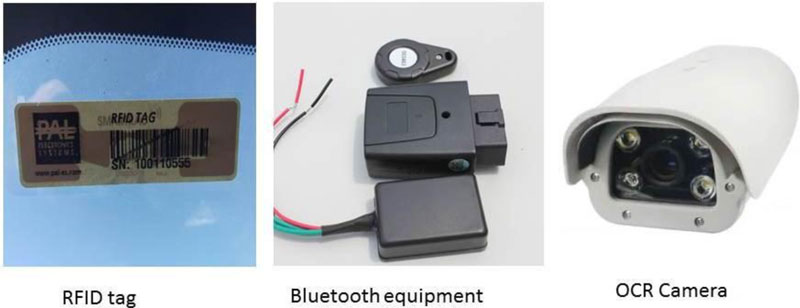
(1) RFID (Radio Frequency Identification) devices are able to identify tags attached to vehicles without human intervention by making use of electromagnetic fields [12]. RFID technology is very fast so it can be also effective in emergency cases [13].
(2) Bluetooth devices make use of UHF radio waves for exchanging information over a short distance. In our case, the information exchange is between a vehicle and a device attached to the parking lot gateway [14].
(3) OCR (Optical Character Recognition) devices can identify vehicles by reading their license plates. OCR devices can understand the numbers by image processing techniques [15].
The three practices are essential because errors can sometimes happen – a vehicle can be mistakenly identified as a different vehicle or a vehicle can be undetected. If such identification incidents occur, the parking lot operator might have a loss. Furthermore, if an incorrect vehicle is mistakenly identified, the owner or the lessee of the incorrect vehicle will be required to go to the trouble of proving that he does not have to pay the wrongly charged payment.
Fig. (1) shows the techniques used in the conjoint vehicle license plate identification system.
3. METHODS
3.1. Putting Into Practice the Conjoint System
Intelligent Transportation Systems are usually implemented using state machines and the suggested conjoint license plate identification system in this paper is no exception. The state machine of the conjoint license plate identification system is in charge of deciding which identification device out of OCR, RFID and Bluetooth will be considered as correct, if a conflict occurs.
RFID is the most reliable technique [16-18]. RFID has an average low error bit rate of typically less than 0.01% [19]. Bluetooth is less reliable than RFID as it has a typically average error bit rate of 0.1% [20], whereas OCR is the least reliable technique as it has an average error bit rate of 3.6% [21] which is the highest error bit rate of the three techniques we use.
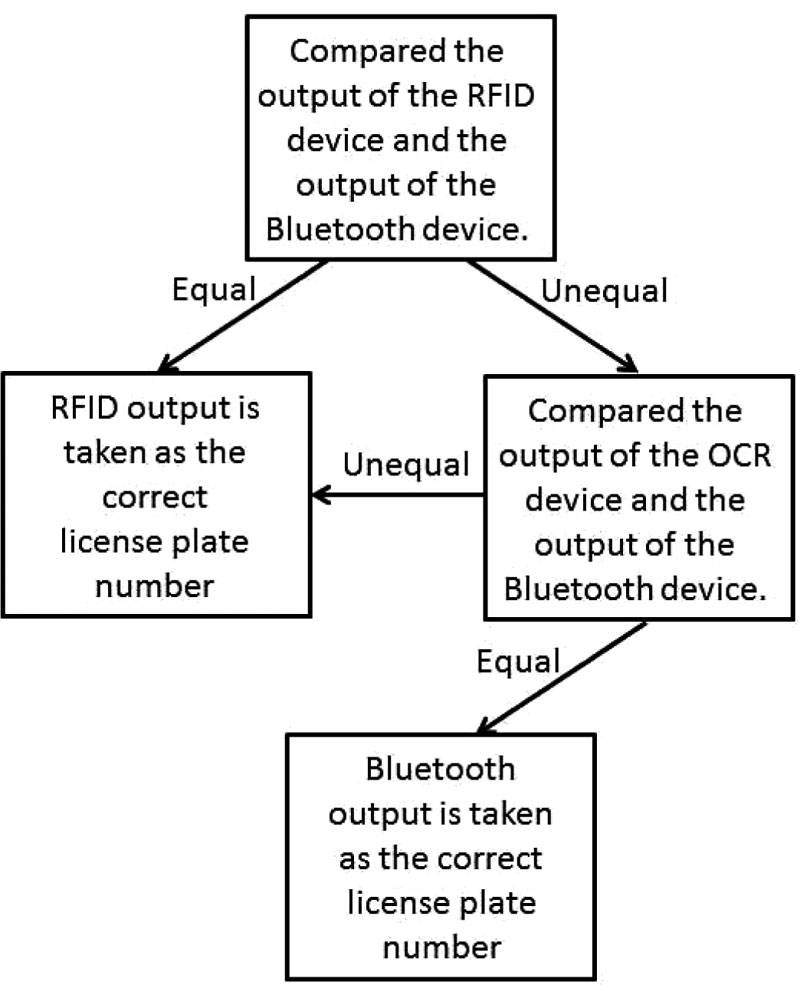
The state machine of the conjoint license plate identification system decides which of the three techniques' output will be sent as the correct license plate number. Because the RFID and the Bluetooth have a better error bit rate, the system first of all looks at their outputs. Only if the outputs of the RFID device and the Bluetooth device are different, the output of the OCR device will be checked .
The conjoint license plate identification system algorithm is summarized in the flow chart depicted in Fig. (2).
Accordingly, the state machine of the conjoint license plate identification system is depicted in Fig. (3). The different devices have different response times as explained below, so multiple states occur as input, so the sampling of the device output is delayed until this output becomes stable.
Specifically, the conjoint license plate identification system algorithm includes the following:
- Obtain the outputs of the RFID device and the Bluetooth device.
- We use an implementation of 0.5MHz clock rate [22];the Bluetooth device is not able to produce the output so fast. In fact, it takes the Bluetooth device approximately 7.38μs to produce the output. Accordingly, the state machine has four “get” states with the purpose of synchronizing the output produced. With 0.5MHz clock rate, four states take 8μs which is more than the 7.38μs required for the Bluetooth device to produce the output. There are other faster Bluetooth devices and if another system uses one of these faster Bluetooth devices, the number of the “get” states can be reduced into a smaller number than four.
- The output of the RFID device and the output of the Bluetooth device are compared to verify that they are equal.
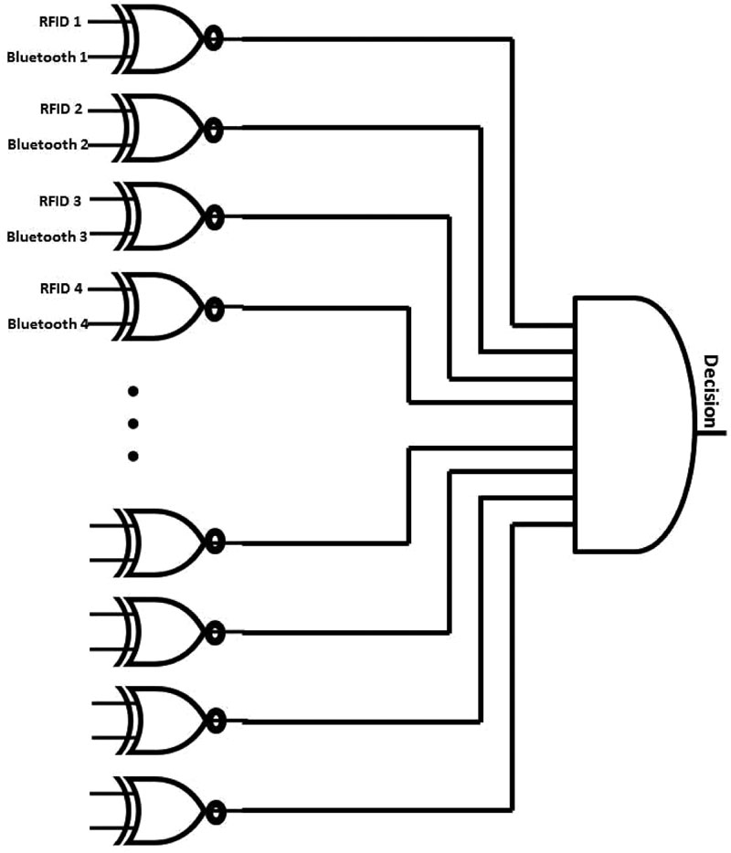
- Usual comparator circuits [23] can also detect which number is greater and which number is smaller; however, we use a simple comparator that can only give a Boolean answer whether the outputs are equal or not. The simple comparator is depicted in Fig. (4):
- If the comparator finds that the RFID output and the Bluetooth output are equal, no further check will be done and the RFID output is taken as the correct license plate number. As mentioned above, the RFID device and the Bluetooth device are more accurate than the OCR device, so even if the output of the OCR device is different, the OCR output can be discarded.
- Else, if there is a mistake either in the RFID output or the Bluetooth output, the system then finds which device has a mistake by checking the output of the OCR device. The device that produces the same output as that of the OCR device is assumed to have the correct output.
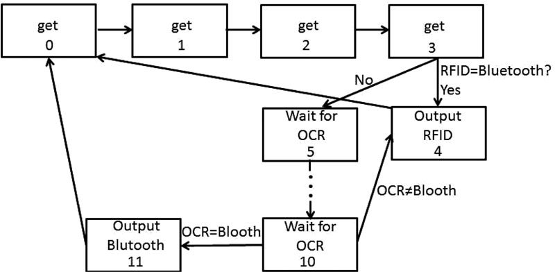
o OCR devices are much slower, specifically producing the output in 21.42μs, therefore the system requires eleven clock cycles; however, the system activates the OCR device along with the activation of the RFID device and the Bluetooth device. If the system finds after four cycles that the RFID device and the Bluetooth device give the same output and the OCR output is no longer needed, the OCR device operation can be stopped. Nevertheless, if the RFID device and the Bluetooth device give different outputs and the OCR device is needed for the final choice, the system will wait for only seven more cycles besides the four cycles that the system has already waited for the Bluetooth device.Therefore, there is no need to wait for dedicated eleven cycles for the OCR device output.
- If the three different devices produce three different outputs, the system will take the output of the RFID device as the correct license plate number. As mentioned above, the RFID device is the most reliable device, so the system will prefer its output. Only if both the Bluetooth device and the OCR device agree on a license plate number, the system will take the output of the Bluetooth device and the OCR device as the correct output.
4. RESULTS
The conjoint license plate identification system has a number of output bits:
- Decision bit indicates whether the system has finished the operation and come to a conclusion what the license number is so the output bits contain the data and can be read. When the system comes to a conclusion what the license number is, this bit will be 1; otherwise this bit will be 0.
- Enable bits for the RFID output and the Bluetooth output decide which output should be forwarded. When the decision bit indicates that the operation of the system has not been completed yet, the values of the enable bits will be “don't care” because the enable bits will not be read in this phase. Just when the decision bit indicates that the operation of the system is completed, the enable bits will be set to their values. The enable bit of the selected device will be set to one, whereas the other bit will be set to zero. Just the RFID device and the Bluetooth device have an enable bit. The OCR device does not need an enable bit, because its output is never taken. The OCR output will be only needed when a selection between the RFID output and the Bluetooth output is required. If the OCR output is equal to one of them, the correct number will be anyway available in the other device. If the OCR output is not equal to the RFID output, nor is it equal to the Bluetooth output, the RFID output will be taken. Therefore, the OCR output is actually never taken and thus no enable bit is needed for it.
- Output bits contain the license plate number of the vehicle that enters the parking lot.
As presented above, the conjoint license plate identification system has a state machine with 12 states, so the implementation of its state machine is by 4 Flip-Flops that represent the binary values of 0000 to 1011. We will denote these Flip-Flops as FF3, FF2, FF1, FF0 where FF3 is the most significant bit and FF0 is the least significant bit.
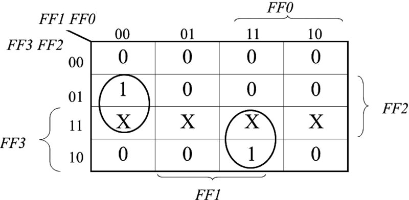
The values of the decision bit are detailed in the Karnaugh map [24] in Fig. (5) which yields the function:
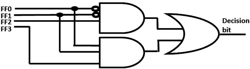
Decision bit = FF2·FF1'·FF0'+FF3·FF1·FF0
Accordingly, the circuit of the decision bit is depicted in Fig. (6).
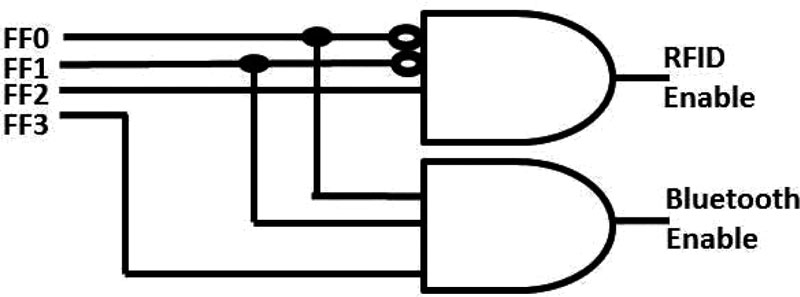
The RFID enable bit function and the Bluetooth enable bit function can be also obtained from this Karnaugh map.The RFID enable bit function is the left group containing cell 0100 and cell 1100, whereas the Bluetooth enable bit function is the right group containing cell 1011 and cell 1111. Accordingly, the enable bit functions are:
RFID enable bit = FF2·FF1'·FF0'
Bluetooth enable bit = FF3·FF1·FF0
Therefore, the circuit of the enable bit functions is very similar to the circuit of the decision bit function. The circuit is depicted in Fig. (7). As mentioned above, no enable bit is needed for the OCR because its output is never taken.
5. DISCUSSION
The conjoint license plate identification system comprises of 12 states, hence it should contain [Log212] Flip-Flops which are [3.5849625] i.e. four Flip-Flops. Therefore, the system has four next state functions – one function for each of the Flip-Flops. Similar to the output bits, Karnaugh maps have been used to get the minimal functions for implementing the next state circuits. We also have chosen to employ Edge-Triggered D-Filp-Flops [25, 26] with the aim of a straightforward implementation.
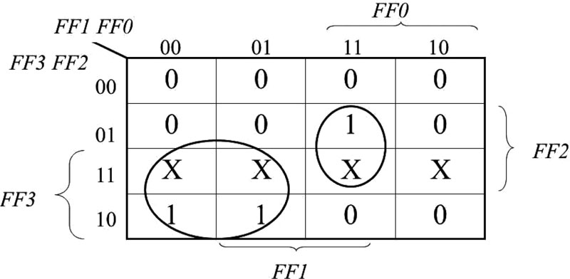
The Karnaugh map for the most significant bit namely FF3 is shown in Fig. (8). States number 12 to number 15 do not exist, so they are denoted as “don't care” with the letter X. The next state i.e. state number 10 is dependent on the comparison of the OCR output and the Bluetooth output. If these outputs are equal, the next state will be state number 11, where F3 is set to 1; otherwise, the next state will be state number 4, where F3 is set to 0, so state number 10 was marked as 0 in the Karnaugh map and the condition OCR=Bluetooth was added to the final form of the function after extracting the function from the Karnaugh map. Therefore, the next state function for F3 is:
NextFF3=FF3·FF1'+FF3·FF2·FF1+FF3·FF2'·FF1·FF0'·OeB
Where OeB stands for the Boolean condition of whether the OCR output is equal to the Bluetooth output.
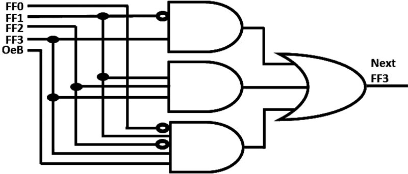
Accordingly, the logic circuit for the next state of FF3 is depicted in Fig. (9).
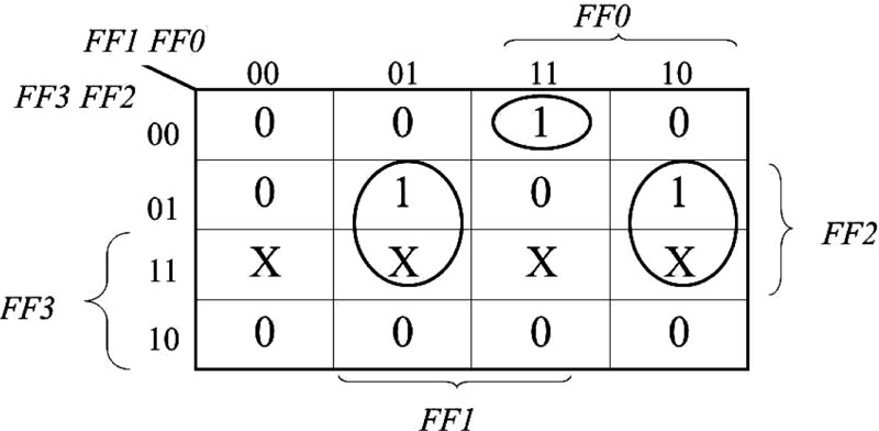
Similarly to FF3, in the Karnaugh map of FF2, states number 12 to number 15 do not exist, so they are denoted as “don't care” with the letter X.The next state of state number 10 is also similar to FF3 as it depends on the comparison of the OCR output and the Bluetooth output; however, unlike FF3, in the next state function for FF2, the next value will be 1 if OCR≠Bluetooth. Therefore, the next state function for F2 is:
NextFF2=FF2·FF1'·FF0+FF3'·FF2'·FF1·FF0+FF2·FF1·FF0'+FF3·FF2'·FF1·FF0'·OeB'
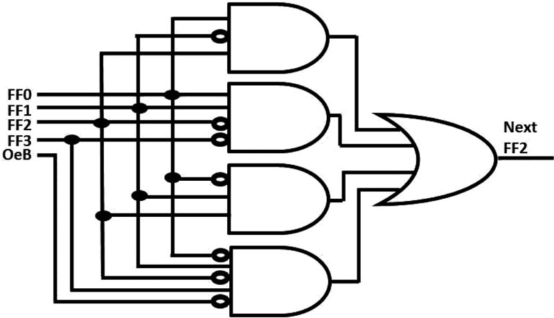
The Karnaugh map of FF2 is shown in Fig. (10), whereas the logic circuit for the next state of FF2 is depicted in Fig. (11).
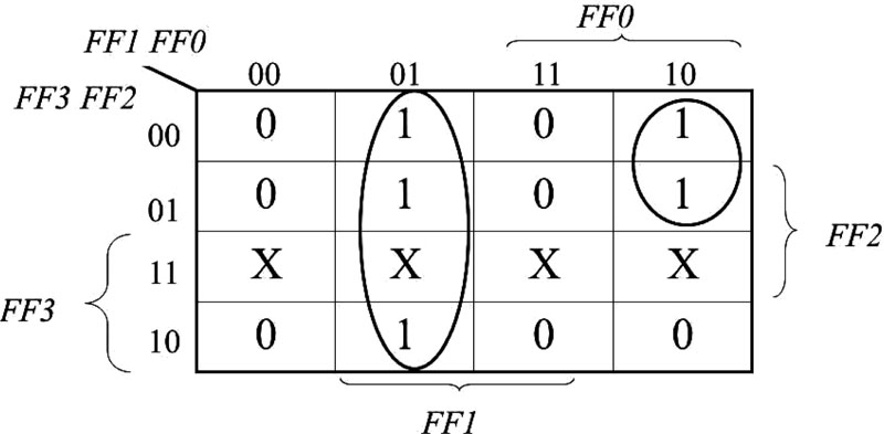
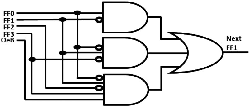
Like FF3 and FF2, the “don't care” states and state number 10 of FF1 are handled in a similar way. The Karnaugh map of FF1 is shown in Fig. (12) and accordingly, the next state function for FF1 is:
NextFF1=FF1'·FF0+FF3'·FF1·FF0'+FF3·FF2'·FF1·FF0'·OeB
Therefore, the logic circuit for the next state of FF1 is shown in Fig. (13).
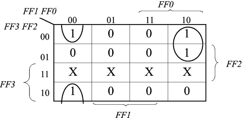
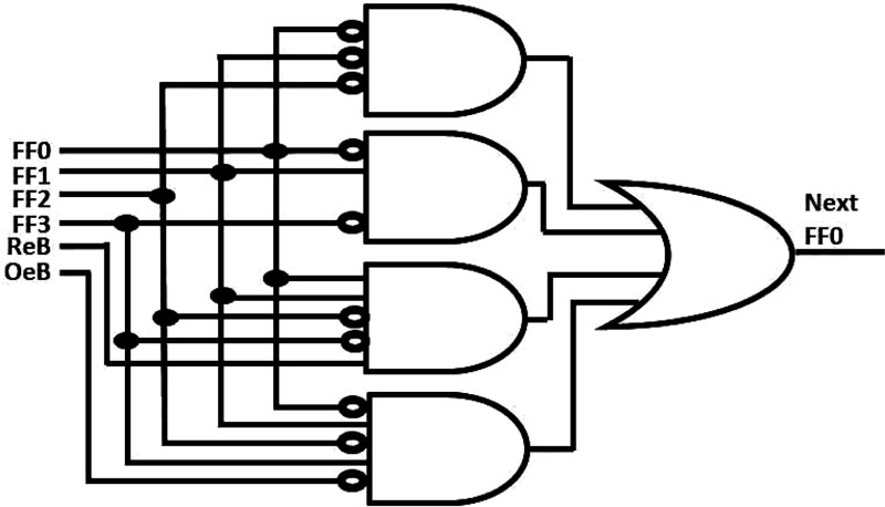
The least significant bit is FF0. FF0 handles the “don't care” states and state number 10 in the same way as they are handled by FF3, FF2 and FF1.The next state of state number 3 is dependent on the comparison of the RFID output and the Bluetooth output, therefore state number 3 was marked as 0 in the Karnaugh map and the condition RFID=Bluetooth was added to the final form of the function after extracting the function from the Karnaugh map. Therefore, the next state function for F0 is:
NextF0=FF2'·FF1'·FF0'+FF3'·FF1·FF0'+FF3'·FF2'·FF1·FF0·ReB+FF3·FF2'·FF1·FF0'·OeB
Where ReB stands for the Boolean condition of whether the RFID output is equal to the Bluetooth output. The Karnaugh map of FF0 is shown in Fig. (14), whereas the logic circuit for the next state of FF0 is shown in Fig. (15).
6. FUTURE DIRECTION
When taking images of license plates in poor environmental conditions such as fog, haze or smog, the quality of these images can be distorted. In addition, magnetic fields can harm the quality of RFID and Bluetooth output. Some techniques have been suggested in order to improve such images. For e.g., Kaur et al. [27] and Singh et al. [28] suggested a technique of Gradient Channel Prior (GCP) in order to overcome various problems such as texture or color distortion and edge degradation.
Security is also an important concern of the proposed model since the proposed model can sometimes unintendedly let hackers obtain some information from the system. Kaur et al. [29]suggest a technique for image encryption that can be helpful to keep the information secure . In the future, we consider adding these techniques.
CONCLUSION
Parking lots for autonomous vehicles will be of low cost [30, 31]. These parking lots will be in remote locations where the lands are inexpensive. In addition, autonomous vehicles will be able to park very close to the adjacent vehicle and will be able to park completely straight, so their parking lots will be very efficient and low-priced.
A critical difficulty is to make sure that the autonomous vehicle is correctly identified at the gate, because the vehicle will be unoccupied so no one will be of assistance for the gatekeeper.
The issue of reliable identification is also very important for vehicle theft prevention. Traditionally, a vehicle thief would have to physically drive the vehicle, so when a vehicle owner reports the vehicle as stolen, the police can either track the thief or the vehicle; however if the stolen vehicle is an autonomous vehicle, the thief will be able to remotely thieve a vehicle [32], so it will be a more challenging task to track the thief, therefore a reliable automatic vehicle identification turns out to be even more important.
The conjoint vehicle license plate identification system can ensure a high level of reliability by identifying the vehicle with three different techniques: RFID, Bluetooth and OCR.
CONSENT FOR PUBLICATION
Not applicable.
AVAILABILITY OF DATA AND MATERIALS
Not applicable.
FUNDING
None.
CONFLICT OF INTEREST
The author declares no conflict of interest, financial or otherwise.
ACKNOWLEDGEMENTS
Declared none.