All published articles of this journal are available on ScienceDirect.

Adaptive Frame of Universal Vehicle Course
Authors Info & Affiliations
Abstract
Background:
Motor vehicles play an important role in the economies of many countries, providing efficient means of transporting goods and people. These vehicles can also have significant impacts on safety, infrastructure and the environment.
Methods:
The design of the suspension affects the vehicle's performance, in terms of the drive, damage to infrastructure, the working space of the suspension, power, and stability against overturning, stability against yaw, braking, and traction.
Results:
The article considers the types and methods of application of adaptive suspensions of modern vehicles, justifies the feasibility of their use for various vehicles, such as modern cars, tractors, etc., which allows the usage of these vehicles for traffic in different road conditions - mountainous terrains with a slope of more than 35o, steppe off-road conditions with frontal obstacles up to half the length of the wheel radius.
Conclusion:
The existing control schemes and prospects for their further development can be improved and intelligent transport systems could be introduced.
1. INTRODUCTION
Suspension is an essential structural part of the vehicle. It is directly related to the body and the engine of the vehicle. It is a set of mechanisms that, working together, connect the frame and wheels of the car. In simple terms, the purpose of the suspension is to ensure smoothness, precision and safety while driving.
The main requirements for the link between body parts and vehicle axles include:
(1) Ensuring the elasticity of the vehicle running, namely: the lack of slopes in turns, swinging during braking, etc.
(2) Adjusting vehicle oscillations by transferring forces from the wheels to the frame.
(3) Ensuring minimal changes in the alignment of the wheel mechanism.
Throughout the development process of a vehicle suspension system, designers always have to solve the problem of matching two groups of conflicting requirements [1]:
(1) Requirements to ensure a given level of smoothness, speed, minimize dynamic loads acting on the load, components, passengers and drivers of the vehicle;
(2) Requirements for handling, safety, stability, stabilization of the vehicle, stabilization of its body.
In addition, it is well known that reconciliation of the conflicting requirements mentioned above can only be most effectively achieved if the following three conditions are met:
(1) The vehicle suspension system should contain an elastic element with a non-linear characteristic [2].
(2) The vehicle suspension system must include an adaptive shock absorber with the ability to control its operation in accordance with the road situation when the vehicle is moving.
(3) When designing a vehicle suspension system, it is necessary to ensure optimal coordination of the operational parameters of the elastic element with a non-linear characteristic and the adaptive shock absorber of the vehicle suspension, as well as to implement the optimal adaptive shock absorber control algorithm.
Analysis of existing approaches to solving this problem in the field of transport engineering showed that there is no optimal, economically acceptable solution for the practical implementation of the above requirements, as well as the implementation of these three conditions [3-6]. However, it seems that the implementation of our proposals will allow us to significantly advance towards solving this complex problem [7-12].
2. LITERATURE REVIEW
Chen et al. [13, 14] investigated an autonomous active suspension control system in which one engine is used to generate electricity and the other to control vibration. Nakano et al. [15] also investigated the self-regulation of vibration using a single motor, in which a variable resistor, charging capacitor, and relay switches were used to control the motor force to follow the required skyhook attenuation force. Wang et al. [16, 17] proposed an active-regenerative control for suspension, in which energy is regenerated at high driving speed and active control is used to provide damping at low speed when the regenerative voltage is lower than the battery voltage.
Gysen et al. [18] developed an electromagnetic regenerative suspension by modifying the shock absorber with a permanent magnet and coil. Gupta et al. [19] and Zuo et al. [20] implemented electromagnetic regenerative suspension in the vehicle suspension and experimentally investigated its performance. They used a 1:2 regenerative suspension prototype and could regenerate 16-64 watts of power at an RMS speed of 0.25-0.5 m / s. Omar et al. developed a hydraulic regenerative shock absorber by combining a hydraulic system and a rotating electromagnetic generator [21]. The influence of fluid viscosity on the transmission of hydraulic energy was explored by Avadhani [22]. The industry has also tried to put active suspensions into practice, using some of the vibration energy and reducing energy consumption. For example, Levant Power Corporation [23] manufactured a regenerative rotary shock absorber called the GENSHOCK and tested the GENSHOCK by incorporating it into a Humvee suspension running on a standard road. It can regenerate the capacity of 500 watts. Another example would be a feature in the active suspension of the Bose [24], equipped with regenerative power amplifiers that allow the return of power from the engine.
Pickelman et al. [25] developed a regenerative shock absorber using a piezoelectric material mounted on the top of the shock-absorbing cylinder. Arizti [26] investigated the use of multilayer piezoelectricity for a regenerative shock absorber. The reaction of a regenerative shock absorber with multilayer piezoelectricity due to shock and harmonic excitations is mathematically modeled and simulated. The regenerated electricity is 17.69 MV, which is less than what typical electromagnetic regenerative shock absorbers would produce. However, the use of piezoelectricity has some advantages, such as its compatibility and size.
This article proposes an adaptive suspension of modern vehicles with a feasibility study, which can be used for various vehicles, such as modern cars, tractors, etc., which makes the usage of these vehicles possible to drive in different road conditions such as mountainous terrain with a slope of more than 350.
3. TYPES OF SUSPENSION
There are many types of suspension. Which one of them is installed on a specific vehicle depends on the drive, vehicle class and other features. The most popular are the following:
- MacPherson. The type of suspension is named after the creator of Earl MacPherson. It consists of a lever, shock absorber and stabilizer. In this type, each wheel is equipped with a lever and attached to the body by means of hinges. Such suspension has a simple design, is quite reliable and inexpensive to maintain and install. The disadvantage of this design is the change of wheel alignment parameters due to the design peculiarities of the shock absorber.
- Double-lever. It has a more ergonomic design consisting of two levers with different parameters. Due to the double action, the greatest resistance to road irregularities is provided as a result of stability and minimum tire wear.
- Multiple. In fact, it is an improved double-lever suspension. It consists of a sub-frame on which levers, supports and hinges are mounted, providing excellent smoothness of the movement, creating a thruster effect and improved resistance to road irregularities. Among the downsides of this design, it is possible to note its high price and a certain difficulty in replacing it.
- Adaptive. It consists of stabilizers, shock absorbers, control unit and sensors. The most “intelligent” variant of suspension is an independent analysis of the situation with the help of sensors that transmit the signals to the stabilizer and shock absorber. Such suspension allows you to customize the car for a specific driver, provides the best safety and stability during operation. The first three variants of design relate to an independent type of suspension, which implies the independence of the right and left wheels. Adaptive suspension is called active in another way, i.e. with the possibility of changing the parameters depending on the circumstances.
The dependent type of suspension has lost its popularity due to the lack of comfort while driving. It consists of a transverse beam, four longitudinal levers and two screw springs. In this version of the suspension, all wheels are dependent on each other. When the position of one wheel changes in relation to the road surface, the angle of collapse of other wheels changes. This is strongly felt when cornering and on rough roads, and can cause skidding and instability when driving. Independent construction has practically not been used in the automotive industry in recent years.
There is an intermediate version of the running auto mechanism - a semi-independent suspension consisting of two longitudinal levers connected to the crossbar. This type is used in all-wheel drive vehicles.
The considered kinds and types of suspension structures are most widely applied mainly in the automotive industry. However, this list is far from complete.
The reason for the emergence of the problem - the creation of a new design of an adaptive frame for the vehicle means, regardless of the frame design of modern cars, tractors and other ground-based tractors, is the use of these machines for driving under different conditions of the road surface - on mountainous terrains with a slope of the surface more than 350, steppe conditions of impassability with frontal obstacles up to half the length of the radius of the wheel. In the first case, i.e. mountain slopes, wheeled cars with one rigid frame lose vertical stability of the stroke, and often fall on the side [1]. Moreover, in the second case, i.e. in the conditions of steppe impassability, all the road surface irregularities simultaneously and randomly acting from all four sides of the frame deform its construction. In addition, the entirety of the vehicle is experiencing a vibration effect, which is the cause of intensive wear and tear of all engine components and assemblies. The driver and passengers also experience complete discomfort in the midst of driving. Secondly, the anatomical structure of four support vehicles with one rigid frame does not meet the requirements of driving stability of the course according to the Somov-Malyshev formula [26].
Therefore, it is necessary for vehicles of universal course to install an adaptive frame consisting of a mechanism that converts the interacting forces of the wheel with the obstacles of the support surface, isolating the spar with the body from any impact of the support part while maintaining the vertical stability of the machine.
4. METHODS OF ADAPTIVE FRAME OF UNIVERSAL VEHICLE COURSE DESIGN
The design of the frame of vehicles intended for work on the inclined surface of the support has to be composite, i.e. must consist of mechanisms with several degrees of mobility, which are adapted to control several independent effects of external force factors. In this case, the external force factors are the force effect of the drive (engine) on the chassis mechanism and the force of interaction of the support point of the chassis mechanism with the irregularities of the road support surface (counteraction of the road surface to the chassis mechanism). Such an arrangement of the vehicle frame is called an adaptive frame or a frame that adapts to the shape peculiarities of the road’s supporting surface.
Research on the structure of adaptable mechanisms of the chassis is carried out by the research laboratory of the department “Transport engineering, mechanical engineering and standardization” of the Kazakh University of Railway Transport.
One of the adaptive mechanisms of the chassis is a parallelogram mechanism that serves as a component frame of the chassis.
Fig. (1) shows the kinematical scheme of the adaptive self-propelled chassis which consists of two half frames 1 and 2 on which two transverse bars 3 and 4 of the same length are hinged on the end sides, forming the half-frames 1 and 2 with the upper part of parallelograms “abcd”, and four supporting walking wheels - 5, 6, 7 and 8 hingedly installed in the lower part of the half-frames 1 and 2. In order to ensure that both frames 1 and 2 are always maintained in an upright position, irrespective of the gradient of the road surface, the bodywork 9 is hinged on the middle part of the transverse bars 3 and 4, where the mass G of the vehicle is concentrated (the engine with transmission mechanisms and the hinged device for installation of working bodies of the processing tools implement).
The installed ‘ef’ rod on the middle part of bars 3 and 4 is rigidly connected to the body 9. Therefore, it is the heaviest part of the chassis.
When driving on the uneven surface of the road in Fig. (2), the chassis mechanism is controlled by the massive element 9 together with the ef rod, because the massive body part always remains in an upright position.
As a result, the direction of the weight force vector G will not be able to leave the support pad tt-t′ t′, formed by four support wheels, eliminating the rollover chassis with large gradients of a reference platform.
This property of the chassis mechanism is similar to the principle of preserving the stability of the body of mountain goats on steep rocks. Then the anatomical structure of the chassis mechanism should be believable. The scheme of the chassis mechanism (Figs. 1 and 2) consists of eight solid elements (links); half frames 1 and 2, walking wheels 5,6,7 and 8 and crossbars 3 and 4, so the total number of links is 8.
These elements are interconnected by 8 single-movable hinges (a,b,c,d,k,n,m,L) (single-movable kinematic pairs).
Therefore, the number P_1= 8. Four support-walking wheels (5,6,7 and 8) form five movable kinematic pairs -P_5 with the road surface. So P_5= 4. Then the total number of chassis mechanism mobility is equal to:
 |
(1) |
Two hinges e and f are the elements of passive coupling –the ef rod. Therefore, they are excluded. The mobility of chassis mechanism W=4 must be controlled by four external devices. Otherwise, the mechanism will have either excessive mobility or superfluous communication. In both cases, the mechanism will definitely not work.
In this case, a drive (motor) will be installed on the chassis with transmission devices that drive the two wheels of the half-frames 1 and 2. During the rotation of the chassis, the clutch of one of the leading wheels of the semi-frames 1 and 2 (direct move and turn) is switched off.
Thus, two of the four mobilities are controlled by a drive (straight running and turn). And two chassis mobilities, in two planes zz и zˏzˏ - overturning relatively extreme pillars (wheels), is controlled by weight G, which always creates more momentum than external impact.
Thus, the mechanism of the chassis is uniquely controlled by the drive and its own weight G when driving an inclined surface.
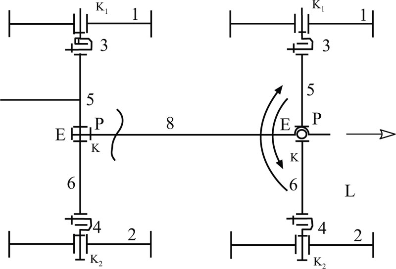
The work of a new design of the adaptive frame of vehicles with a universal stroke (Fig. 3), which consists of three nodes - the mechanisms of the rear and front axles and the spar chain, is outlined below.
Fig. (4) shows the general kinematic diagram, consisting of two wheels 1 and 2, freely rotating on the axles of the hubs 3 and 4, made in the form of lateral sides of the AVSD parallelogram, and two transverse sides 5, 6 are parallel to the axes of the hubs, passive connection 7, made in the form of an additional lateral side of the EP parallelogram. The scheme of the rear axle mechanism (Fig. 4) is mounted on a horizontal supporting surface xx. The thin line shows another position of this mechanism’s scheme, modified by the irregularity of the supporting surface of the road x1x1. At the moment when wheel 2 rallies to the top of the unevenness of the support and rises, the first wheel 1 moves along the xx plane, keeping the vertical positions of the wheels 1 and 2, as well as all lateral sides of the parallelogram.
Now lets see how the anatomy of the mechanism scheme is formed by the formula of Somov - Malyshev. The number of moving links n=6, and the additional side of the EP parallelogram is considered a passive element of the scheme. Therefore, the number of links and kinematic pairs of this link are not taken into account. And the number of single motion kinematic pairs Р_1 (А,В,С,D,К_1,К_2) is also equal to six, i.e., P 1=6. Reference points О1 and О2 are pairs Р5 =2. Then:
 |
(2) |
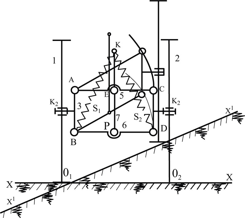
where, one mobility scheme is a rectilinear motion along the longitudinal axis (perpendicular to the plane of the scheme), and the other – rotation of the parallelogram scheme ABCD around the K1K2 axis, the third mobility is the rotation of the rear axle around the reference point О1 or О2 relative to the vertical axis, the coordinates and the fourth mobility is the rotation of the parallelogram ABCD scheme together with the wheel 2 relative to the AB side (thin lines).
To eliminate the mobility of the circuit with respect to two points О1 и О2, we install elastic suspensions S1 and S2 in the form of two springs. On the ends of these springs S1 and S2, we connect the point K, and connect the other ends with the hinges B and D of the parallelogram ABCD. Then, the scheme of the mechanism loses this mobility, since when the sides of the parallelogram are rotated, the spring P_1 stretches, and the tension of the spring P_2 weakens. In addition, the weight of the frame of the machine also pulls by its moment, increasing the tension of the spring P_1. As a result, the loss of this mobility, connected by the parallelogram property, the mechanism scheme, acquires another mobility, contributing to climbing an obstacle, keeping the vertical positions of the wheel’s plane. We call this mobility adaptive mobility.
5. RESULTS
Fig. (3) shows the general scheme of the adaptive frame of vehicles, which consists of a rear axle mechanism that has four types of mobility relative to the road surface, of the front axle which is identical in construction with the rear axle and of the spar chain 8 connecting the rear axle to the front axle through passive elements (passive connections) EP. Moreover, one end of the spar 8 is connected to the front axle mechanism with the help of a single-movable hinge L, which ensures relative rotation of the rear and front axles.
Then, the total mobility of the adaptive frame of the vehicle is determined by taking into account all the links of the general scheme (Fig. 3).
The number of moving links of two axels is n = 12, since the number of links of the rear axle 6 and the front axle 6, and the number of single-motion kinematic pairs P_1=13; for the relative rotation of two axels, a single-movable hinge L is introduced, so the sum of the single-movable hinges of two identical axels will be:
 |
(3) |
The spar, as noted above, is a passive element of the scheme. The total mobility of the frame is:
 |
(4) |
For the unambiguous operation of the mechanism, the circuit of the frame, in an independent drive, on each mobility must be installed.
These drives are as follows:
- The motor for straight-line movement; 2) The drive for the relative rotation of the axles; 3) The adaptive drive - the irregularities of the support surface.
In all three cases, the vertical position of the spar frame and the plane of the four wheels is maintained, which ensures the vertical stability of the engine and high riding comfort.
The vertical stability of vehicles used in mountainous conditions is essential for traffic safety. Therefore, the design of the chassis frame of vehicles must be composite. One solution to vertical chassis stability is to use a composite frame of a parallelogram design.
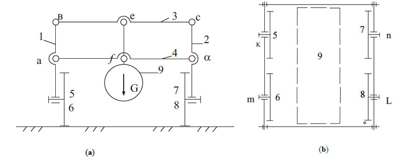
In Fig. (5), the chassis scheme on four supports (with walking wheels) with a parallelogram type acefbd composite frame on a flat supporting surface (Fig. 5a) is shown and on an inclined supporting surface (Fig. 5b). Adding to the device, a parallelogram mechanism of the passive element efc with a load G gives a special property to control the positions of the side half-frames ac and bd. Since the main mass of the chassis is placed on the passive element ef, it controls the positions of the half-frames, keeping them strictly in the vertical position regardless of the unevenness of the supporting surface. Such a composite frame is called an adaptive chassis frame with a parallelogram effect.
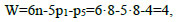
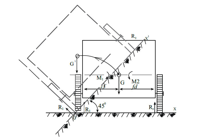
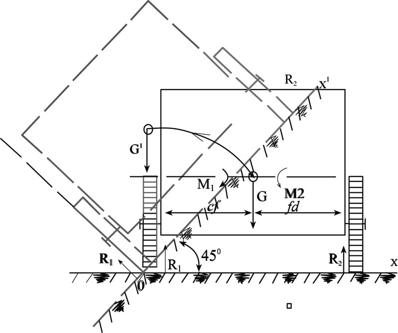
If this scheme turns into a rigid frame, considering that all joints acefbd do not exist, the scheme becomes a frame of the known vehicles (Fig. 6), where it is fair:
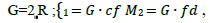 |
(5) |
Where: cf=fd ;1 = M2; R = R1 + R2; R1 = R2.
This is the equilibrium condition of a static system. If this system is put on an inclined plane OX', then (in Fig. (3) shown by dashed lines) the stability corresponds to the following ratio of the above parameters:
 |
(6) |
This means a stable balance is disturbed. The chassis mechanism rotates relative to the left o-O reference line, i.e. it overturns. This change of stability is due to a change in the relative position of the force vectors -R1 → 2 → G →
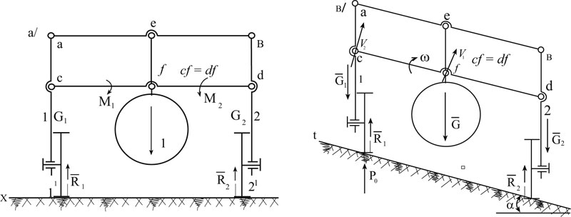
Now the frame installed hinges acefbd are rotated in the parallelogram diagram ( Fig. 5A ) and the chassis is put on an inclined plane as shown in the scheme of the mechanism (Fig. 5b). In this case, the parallelism of the acting external forces and reactions in the supports will not change. The action of the support surface in the form of a force P_0, is distributed over the hinges (Fig. 5b), i.e:
 |
(7) |
Where, P0 −-action of the support surface on the chassis mechanism (H);
V0 − is the speed of a fulcrum O (c); G/2–weight of the first half frame (H); V1 − velocity of the hinge centre – f; V2 − velocity of the hinge centre – c;
G- Weight of a composite frame (H); N- power (energy)  ;
;
The speed of the point "d" is equal to zero, because when the parallelogram mechanism is rotated by the force P0 , the right semi-frame is motionless, i.e.Vd = 0 and therefore
 |
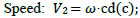 |
(8) |
 |
That is why: V2 = 2 ∙ V1, as well as G = 2 ∙ G1 ; for this reason R1 = G1 и R2 = G2. The reactions in the supports are the same.
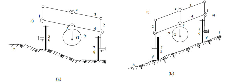
As a result, it can be determined that the adaptive frame is able to adapt to the unevenness of the support surface, i.e. maintain a stable balance of the frame when driving in mountainous terrain (Fig. 7).
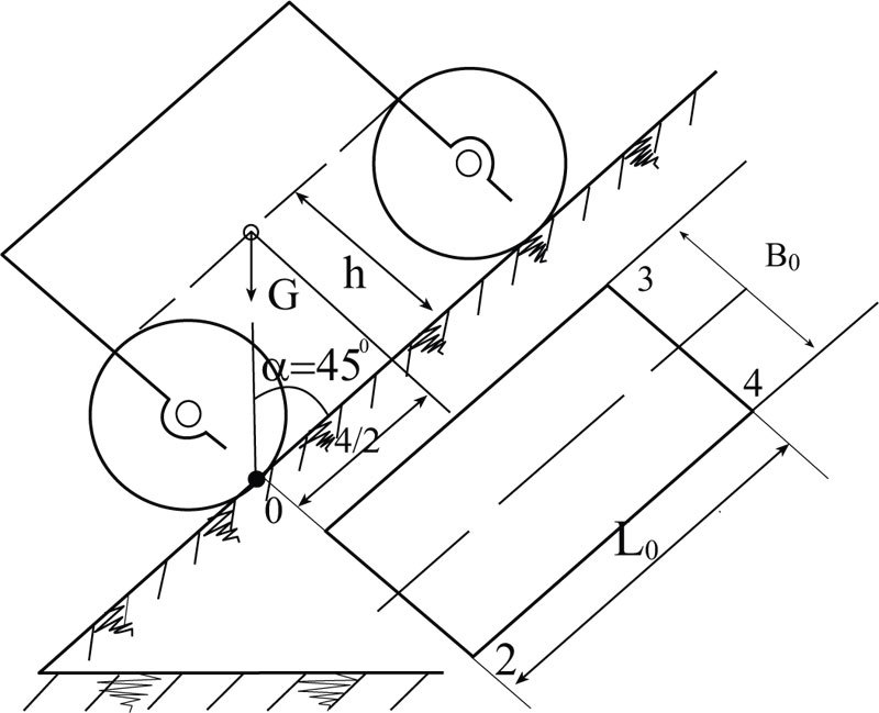
The vertical stability of the vehicle’s chassis still depends on the overall dimensions of the frame, on the size of area 1 2 3 4 of support platforms and the height of the gravity center and the system. Therefore, we establish the main dimensions of the chassis. We call the values critical of the parameters at which the chassis will overturn. These values are L0 − critical value for chassis length (Fig. 8), B0 − critical value for chassis width. The parameters adopted for constructive considerations are defined as chassis parameters. These parameters are: h, the height of the center of gravity and r, the radius of the wheel. As a rule, it is customary to set the minimum values h = 2r.
Lets consider the critical position of the chassis mechanism at the moment of overturning when the angle of inclination of the supporting surface is α=45ͦ^ ͦ. Longitudinal stability will be (Fig. 8):
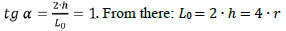 |
(9) |
Transverse stability:  . From there: B0 = 2 ∙ h.
When designing chassis mechanism, schemes are set by valid values [L] and [B], which are equal to:
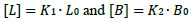 |
(10) |
The coefficients are K1 ≥ 1.5 и K2 ≥ 2.
To adapt the chassis, the value of the coefficient K2 does not make sense, because there is no critical position for this type of chassis.
6. DISCUSSION
The process of interaction of the support part of ground vehicles, in particular the wheel, with the irregularities of the supporting surface of the road, determines the ride comfort and their passability. And the nature of the interaction depends on the design of the wheel and elastic suspension, which softens the impact of bumps on the road surface, perceiving and converting the impact force in the right direction. This creates a high comfort position for the crew part of vehicles. The impact of road surface irregularities that affect the wear of adaptive suspension parts depending on the driver's behavior is eliminated by a symmetrical redistribution of the impact force in two directions, one part of which is perceived horizontally only by the spring, and the other part by the fixed part of the floor frame. In this case, the suspension mechanism in any position maintains an equilibrium position due to the action of balanced systems of forces. Therefore, the adaptive suspension mechanism with a wheel mounted on a half-frame is placed relative to the road surface in the direction of movement in different ways depending on the wheel design. Fig. (9) shows an adaptive suspension with a walking wheel, the half-frame 1 of which is set at an angle of 45 to the road surface from the rear of the wheel 2. With this installation, the impact action of the ground P passes through the normal n-n, the acting force of the weight decreases and, accordingly, the wear of the suspension. The adaptive suspension works normally if:
 |
(11) |
 |
A walking wheel with road irregularities meets at the point "K", located in front of the center of the hub B, so the wheel relative to this point immediately begins to rotate as relative to the instantaneous center. Therefore, the action of the moment will appear at point B as the action of the circumferential force of the Po, depending on the resistance:
 |
(12) |
In this case, the half-frame makes a forward movement. This allows you to ride a walking wheel with high comfort even in off-road conditions, while reducing wear on the adaptive suspension parts depending on the driver's behavior.
CONCLUSION
The article has discussed the types and uses of adaptive suspensions of modern vehicles, the feasibility of their use for various vehicles, such as modern cars, tractors and other ground-based tractors, which allows these vehicles to drive under different road surface conditions – mountain terrains with a slope of more than 350, steppe off-road conditions with frontal obstacles up to half the length of the wheel radius. The existing management schemes and prospects for their further development can be improved and intelligent transport systems can be implemented.
CONSENT FOR PUBLICATION
Not applicable.
AVAILABILITY OF DATA AND MATERIALS
Not applicable.
FUNDING
None.
CONFLICT OF INTEREST
The authors declare no conflict of interest, financial or otherwise.
ACKNOWLEDGEMENTS
Declared none.